What is a Printed Circuit Board (PCB)?
A printed circuit board (PCB) is a flat board made of insulating material like fiberglass, composite epoxy, or other laminate material with conductive pathways etched or “printed” onto the board. It is used to mechanically support and electrically connect electronic components using conductive tracks, pads and other features.
PCBs are inexpensive, and can be highly reliable. They require much more layout effort and higher initial cost than either wire-wrapped or point-to-point constructed circuits, but are much cheaper, faster, and consistent in high volume production.
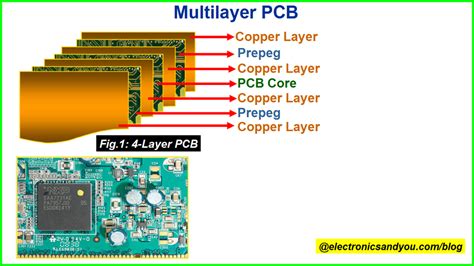
PCBs can be single-sided (one copper layer), double-sided (two copper layers on both sides of one substrate layer), or multi-layer (outer and inner layers of copper, alternating with layers of substrate). Multi-layer PCBs allow for much higher component density, because circuit traces on the inner layers would otherwise take up surface space between components.
What is a Printed Wiring Board (PWB)?
A printed wiring board (PWB) is an older term for a printed circuit board. It literally describes the board as printed wiring.
The main difference between a PWB and a PCB is that a PWB only has copper conductors on the Outer Layers, while a PCB can have them on inner layers as well. Therefore, a PWB can be considered a subset of PCBs – all PWBs are PCBs but not all PCBs are PWBs.

PWB vs PCB – Key Differences
While PWBs and PCBs serve the same general purpose of interconnecting electronic components, there are some key differences between the two terms:
| Feature | PWB | PCB |
|---|---|---|
| Copper layers | Only on outer surfaces | Can be on inner and/or outer layers |
| Density | Lower component density | Higher component density possible with inner layers |
| Terminology | Older term, less commonly used today | More modern, widely used term that includes PWBs |
| Synonymous? | Always refers to a type of PCB | Includes PWBs and other types |
In summary, a printed wiring board is an older term that specifically refers to a flat board with conductive copper pathways printed on one or both outer surfaces to interconnect electronic components. A printed circuit board is a broader, more modern term that encompasses PWBs but also includes boards with additional inner conductive layers.

History and Origin of the Terms
The printed wiring board originated first in the 1920s and 1930s. Before printed circuits, point-to-point wiring was used where each electronic component was connected to other components by individual wires. This was a time-consuming and error-prone manufacturing process.
The idea of printing conductive traces onto an insulating base material to interconnect components had been proposed as early as 1903. The Austrian engineer Paul Eisler fabricated the first operational printed wiring boards in the late 1930s and early 1940s. Around the same time in the United States, the National Bureau of Standards was also developing printed wiring for proximity fuses.
During and after World War II, PWBs started to see widespread use in consumer electronics as well as military applications. As technologies continued to advance, multilayer circuit boards with conductive layers printed on the inner layers (as well as or instead of outer layers) were developed in the 1960s. These allowed for greater wiring density and more compact designs.
To differentiate these newer multilayered boards from the older PWBs, the term printed circuit board (PCB) was adopted to refer to the overall category. However, PWB continued to be used for a time, especially in military documentation. Over the decades, PCB became the predominant term used across industry, while PWB usage declined but can still be found occasionally.

Modern Standards and Terminology
Today, the terms PCB and PWB are sometimes used synonymously, with PCB being much more common. In the electronics industry, standards have converged on printed circuit board (PCB) as the main term that covers all types of boards with printed conductive traces, including both single-sided PWBs and Multilayer PCBs.
For example, the leading international standards organization for electronics, the IPC (formerly Institute for Printed Circuits), almost exclusively uses PCB terminology across their standards and guidelines for Circuit Board Design, fabrication, assembly, and inspection. Relevant standards include:
- IPC-2221: Generic Standard on Printed Board Design
- IPC-6012: Qualification and Performance Specification for Rigid Printed Boards
- IPC-A-600: Acceptability of Printed Boards
While these standards focus on rigid boards, there are also standards for other types of circuit boards like high density interconnect (HDI), flexible circuits, and rigid-flex combinations.
The US military has largely transitioned to using PCB as well, such as in the United States Defense Standard MIL-STD-275 on Printed Wiring for Electronic Equipment. However, older specifications and documentation may still contain PWB.
In summary, PCB is the predominant term used today across the electronics industry to refer to all types of printed boards, while PWB is an older term that is less common but still appears occasionally, especially in legacy specifications. The two are often used interchangeably but technically PWB refers only to single or double-sided boards while PCB includes those plus multilayer boards.
Frequently Asked Questions
1. Are PWB and PCB the same thing?
While PWB and PCB are often used synonymously, they are not exactly the same. A PWB specifically refers to a board with conductive traces printed on one or both outer surfaces, while a PCB is a broader term that also includes multilayer boards with inner conductive layers. So a PWB is a type of PCB, but not all PCBs are PWBs.
2. Which term is more commonly used, PWB or PCB?
PCB is by far the more commonly used term in the modern electronics industry. Most standards, technical documentation, and general discussions will refer to printed circuit boards (PCBs). PWB is an older term that is less common today but can still be found in some legacy specifications and documents, especially military.
3. Does it matter which term I use?
For most general purposes, using either PWB or PCB is acceptable and the two terms are often used interchangeably. However, for technical accuracy, PCB is preferred as the broader term, while PWB should only be used when specifically referring to single or double-sided boards without inner layers. When in doubt, using PCB is the safer choice as it encompasses all types.
4. Are there other types of circuit boards besides PWBs and PCBs?
Yes, there are several other types of circuit boards that fall under the broad category of PCB but have additional unique features. These include:
- High Density Interconnect (HDI): PCBs with a higher wiring density than traditional boards, made possible by using smaller vias and capture pads, as well as finer conductor widths and spacings.
- Flexible Circuits: PCBs made from flexible plastic substrates that can be bent, twisted, and folded to fit in tight spaces or movable parts. Also known as flex circuits.
- Rigid-Flex: Hybrid PCBs that contain both rigid and flexible substrates, allowing the board to be partially bent or folded while still providing rigid support for components.
5. What are the benefits of using a PCB over other interconnect methods?
PCBs provide several key advantages compared to other wiring methods like point-to-point or wire-wrap:
- Repeatability: PCBs can be mass produced with consistent quality, as opposed to manual wiring which is prone to errors and inconsistencies.
- Size and Density: PCBs, especially multilayer ones, allow for much higher component density and more compact packaging than individual wires.
- Reliability: Printed traces are less prone to breaking or coming loose than discrete wires. Solder joints on a PCB are also typically more robust than other types of connections.
- Cost: While PCBs have a higher initial setup cost, they are much cheaper to mass produce than manually wired boards. Automated assembly processes also reduce labor costs.
- Signal Integrity: Proper PCB Design allows for Controlled Impedance traces, ground planes, and other features that can improve signal quality compared to loose wires.
In summary, PCBs have become the standard in electronics manufacturing for good reason, offering superior reliability, consistency, density, and cost effectiveness compared to other interconnect technologies. As PCB technology continues to evolve, even more complex and compact designs will be possible.
No responses yet