Introduction to PCB Visualizer
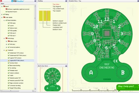
A PCB Visualizer is a powerful tool that allows engineers, designers, and hobbyists to view and analyze printed circuit board (PCB) designs in a user-friendly and interactive manner. With the increasing complexity of modern electronic devices, PCB Visualizers have become an essential part of the design process, helping to streamline workflows and improve the overall quality of PCB designs.
In this article, we will explore the features and benefits of a free new PCB Visualizer tool called Drill & Slot editor. We will discuss how this tool can help you optimize your PCB designs, catch potential issues early in the design process, and ultimately save time and money in the long run.
What is Drill & Slot editor?
Drill & Slot editor is a free, web-based PCB Visualizer tool that allows users to view, analyze, and edit PCB designs directly in their web browser. The tool is designed to be intuitive and user-friendly, making it accessible to both experienced PCB designers and beginners alike.
Some of the key features of Drill & Slot editor include:
- Real-time 3D visualization of PCB designs
- Support for a wide range of PCB file formats, including Gerber, ODB++, and IPC-2581
- Customizable display settings, including layer visibility and color schemes
- Measurement tools for analyzing board dimensions, drill holes, and component placement
- Design rule checking (DRC) for identifying potential manufacturing issues
- Collaborative features for sharing and reviewing designs with team members

Benefits of using a PCB Visualizer
1. Improved Design Quality
One of the primary benefits of using a PCB Visualizer like Drill & Slot editor is the ability to catch potential design issues early in the development process. By visualizing your PCB design in 3D, you can easily identify problems such as component clearance issues, improper drill hole sizes, or incorrect layer stackups.
Catching these issues early can save significant time and money in the long run, as it is much easier and less expensive to make changes to a design before it goes to manufacturing.
2. Faster Iteration and Collaboration
PCB Visualizers also make it easier to iterate on designs and collaborate with team members. With Drill & Slot editor, you can share your PCB design with others by simply sending them a link to the web-based tool. This allows multiple team members to view and analyze the design simultaneously, providing feedback and suggestions in real-time.
Additionally, the ability to quickly make changes and see the results in 3D can help speed up the design process, allowing you to iterate on your design more efficiently.
3. Improved Communication with Manufacturers
When it comes time to send your PCB design to a manufacturer for production, a PCB Visualizer can help ensure that your design is accurately communicated and understood. By providing your manufacturer with a 3D visualization of your design, you can clearly convey your requirements and catch any potential issues before the design goes to production.
This can help avoid costly mistakes and delays in the manufacturing process, ultimately saving time and money.

How to use Drill & Slot editor
Using Drill & Slot editor is straightforward and intuitive. To get started, simply visit the web-based tool and upload your PCB design file. The tool supports a wide range of file formats, including Gerber, ODB++, and IPC-2581.
Once your design is uploaded, you can use the various display settings and tools to analyze and optimize your design. Some of the key features and tools include:
1. Layer Visibility and Color Settings
Drill & Slot editor allows you to customize the visibility and color of each layer in your PCB design. This can be helpful for focusing on specific aspects of your design, such as the component placement or routing layers.
To adjust the layer visibility and color settings, simply click on the “Layers” tab in the left-hand menu and use the checkboxes and color pickers to customize your display.
2. Measurement Tools
Drill & Slot editor includes a range of measurement tools for analyzing the dimensions and placement of various elements in your PCB design. These tools can be accessed by clicking on the “Measure” tab in the left-hand menu.
Some of the key measurement tools include:
| Tool | Description |
|---|---|
| Distance | Measure the distance between two points on the board |
| Radius | Measure the radius of a circular element, such as a drill hole or pad |
| Angle | Measure the angle between two lines or edges |
| Area | Measure the area of a selected region on the board |
3. Design Rule Checking (DRC)
Drill & Slot editor includes a built-in design rule checking (DRC) tool for identifying potential manufacturing issues in your PCB design. The DRC tool can be accessed by clicking on the “DRC” tab in the left-hand menu.
The DRC tool checks your design against a set of predefined rules, such as minimum trace width, minimum clearance between components, and minimum drill hole size. If any violations are found, the tool will highlight them on the 3D visualization of your board, allowing you to quickly identify and resolve the issues.
4. Collaborative Features
Drill & Slot editor includes several collaborative features for sharing and reviewing PCB designs with team members. To share your design, simply click on the “Share” button in the top-right corner of the tool and enter the email addresses of the people you want to share with.
Team members can then view and analyze the design in their own web browser, providing feedback and suggestions in real-time. The tool also includes a built-in comment system for leaving notes and feedback directly on the 3D visualization of the board.

Tips for Optimizing Your PCB Design with Drill & Slot editor
-
Use the layer visibility and color settings to focus on specific aspects of your design, such as the component placement or routing layers.
-
Take advantage of the measurement tools to ensure that your design meets all of the necessary dimensional requirements, such as minimum trace width and clearance between components.
-
Run the DRC tool frequently throughout the design process to catch potential manufacturing issues early on.
-
Use the collaborative features to share your design with team members and get feedback and suggestions in real-time.
-
Experiment with different display settings and view angles to get a comprehensive understanding of your PCB design.
Frequently Asked Questions (FAQ)
-
Is Drill & Slot editor really free to use?
Yes, Drill & Slot editor is completely free to use. There are no hidden fees or subscription required. -
What file formats does Drill & Slot editor support?
Drill & Slot editor supports a wide range of PCB file formats, including Gerber, ODB++, and IPC-2581. -
Can I use Drill & Slot editor on my mobile device?
Yes, Drill & Slot editor is a web-based tool that can be accessed from any device with a web browser, including smartphones and tablets. -
Does Drill & Slot editor include a built-in PCB editor?
No, Drill & Slot editor is primarily a visualization and analysis tool. It does not include a built-in PCB editor for creating or modifying designs. -
Can I share my PCB designs with team members using Drill & Slot editor?
Yes, Drill & Slot editor includes collaborative features for sharing and reviewing PCB designs with team members in real-time.
Conclusion
In conclusion, a PCB Visualizer like Drill & Slot editor is an essential tool for anyone involved in the design and manufacture of printed circuit boards. By providing a user-friendly and interactive way to view and analyze PCB designs, Drill & Slot editor can help you catch potential issues early in the design process, iterate on designs more efficiently, and communicate more effectively with manufacturers.
Whether you’re an experienced PCB designer or just getting started, Drill & Slot editor is a powerful and accessible tool that can help you optimize your designs and bring your electronic projects to life. So why not give it a try and see how it can benefit your workflow?
No responses yet