Introduction to Hex Inverters
A hex inverter, also known as a NOT gate or inverting buffer, is a digital logic gate that performs logical negation on each of its six inputs, producing the complementary output. In other words, a high input results in a low output and a low input results in a high output. Hex inverters are widely used in digital electronics to invert signals, provide buffering, and maintain proper logic levels.
Hex inverters are available as integrated circuits (ICs) and come in various families such as TTL (Transistor-Transistor Logic) and CMOS (Complementary Metal-Oxide-Semiconductor). Each family has its own characteristics in terms of speed, power consumption, and drive strength.
Key Features of Hex Inverters
- Perform logical negation (NOT operation) on six independent inputs
- Provide signal buffering and level shifting
- Available in different logic families (TTL, CMOS)
- High noise immunity
- Wide operating voltage range
- High output drive capability
3 Main Types of Hex Inverter ICs
There are three main types of hex inverter ICs commonly used in digital circuits:
- 7404 (TTL)
- 4069 (CMOS)
- 14049 (CMOS)
Let’s explore each type in detail.
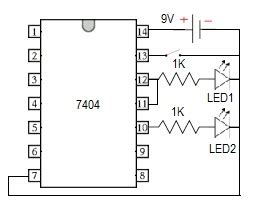
1. 7404 (TTL) Hex Inverter
The 7404 is a popular TTL hex inverter IC. It consists of six independent inverters in a single package. The 7404 operates on a supply voltage of 5V and has a typical propagation delay of 10-15 nanoseconds.
Pin Configuration
| Pin | Function |
|---|---|
| 1 | 1A (Input) |
| 2 | 1Y (Output) |
| 3 | 2A (Input) |
| 4 | 2Y (Output) |
| 5 | 3A (Input) |
| 6 | 3Y (Output) |
| 7 | GND |
| 8 | 4Y (Output) |
| 9 | 4A (Input) |
| 10 | 5Y (Output) |
| 11 | 5A (Input) |
| 12 | 6Y (Output) |
| 13 | 6A (Input) |
| 14 | VCC |
Key Specifications
- Logic Family: TTL
- Operating Voltage: 5V
- Propagation Delay: 10-15 ns
- Output Drive: 10 TTL loads
- Power Dissipation: 80 mW
- Operating Temperature: 0°C to 70°C
Applications
- Signal inversion
- Level shifting
- Pulse shaping
- Buffering
- Interfacing between different logic families
2. 4069 (CMOS) Hex Inverter
The 4069 is a CMOS hex inverter IC that provides six independent inverters in a single package. It has a wide operating voltage range and low power consumption compared to TTL counterparts.
Pin Configuration
| Pin | Function |
|---|---|
| 1 | 1A (Input) |
| 2 | 1Y (Output) |
| 3 | 2A (Input) |
| 4 | 2Y (Output) |
| 5 | 3A (Input) |
| 6 | 3Y (Output) |
| 7 | VSS |
| 8 | 4Y (Output) |
| 9 | 4A (Input) |
| 10 | 5Y (Output) |
| 11 | 5A (Input) |
| 12 | 6Y (Output) |
| 13 | 6A (Input) |
| 14 | VDD |
Key Specifications
- Logic Family: CMOS
- Operating Voltage: 3V to 15V
- Propagation Delay: 60-150 ns
- Output Drive: 10 LSTTL loads
- Power Dissipation: 10 nW per gate (typical)
- Operating Temperature: -40°C to 85°C
Applications
- Low-power digital circuits
- Battery-operated devices
- Interfacing between CMOS and TTL logic
- Schmitt Trigger inputs for noise immunity
- Oscillator and pulse generator circuits
3. 14049 (CMOS) Hex Inverting Buffer
The 14049 is another CMOS hex inverter IC, similar to the 4069, but with higher drive capability and Schmitt trigger inputs for improved noise immunity.
Pin Configuration
| Pin | Function |
|---|---|
| 1 | 1A (Input) |
| 2 | 1Y (Output) |
| 3 | 2A (Input) |
| 4 | 2Y (Output) |
| 5 | 3A (Input) |
| 6 | 3Y (Output) |
| 7 | GND |
| 8 | 4Y (Output) |
| 9 | 4A (Input) |
| 10 | 5Y (Output) |
| 11 | 5A (Input) |
| 12 | 6Y (Output) |
| 13 | 6A (Input) |
| 14 | VDD |
Key Specifications
- Logic Family: CMOS
- Operating Voltage: 3V to 15V
- Propagation Delay: 45-90 ns
- Output Drive: 15 LSTTL loads
- Power Dissipation: 10 nW per gate (typical)
- Operating Temperature: -40°C to 85°C
- Schmitt Trigger Inputs
Applications
- Interfacing between noisy environments and digital circuits
- Squaring up slow-rising signals
- Debouncing switches and contacts
- Generating clean pulses from slow edges
- Improving noise immunity in digital systems

Comparison of Hex Inverter ICs
| Parameter | 7404 (TTL) | 4069 (CMOS) | 14049 (CMOS) |
|---|---|---|---|
| Logic Family | TTL | CMOS | CMOS |
| Operating Voltage | 5V | 3V to 15V | 3V to 15V |
| Propagation Delay | 10-15 ns | 60-150 ns | 45-90 ns |
| Output Drive | 10 TTL | 10 LSTTL | 15 LSTTL |
| Power Dissipation | 80 mW | 10 nW/gate | 10 nW/gate |
| Operating Temp. | 0°C to 70°C | -40°C to 85°C | -40°C to 85°C |
| Schmitt Trigger | No | No | Yes |

Choosing the Right Hex Inverter IC
When selecting a hex inverter IC for your application, consider the following factors:
- Logic Family: TTL or CMOS
- TTL offers faster speed but higher power consumption
-
CMOS provides lower power consumption and wider voltage range
-
Operating Voltage
-
Ensure the hex inverter is compatible with your system’s supply voltage
-
Speed and Propagation Delay
-
Consider the required speed and propagation delay for your application
-
Output Drive Capability
-
Determine the number and type of loads the hex inverter needs to drive
-
Power Consumption
-
Evaluate the power budget and choose an IC that meets your power requirements
-
Noise Immunity
-
For noisy environments, consider hex inverters with Schmitt trigger inputs
-
Operating Temperature Range
- Select an IC that operates reliably in your application’s temperature range

Hex Inverter Application Examples
Hex inverters find use in a wide range of digital circuits and applications. Here are a few examples:
1. Signal Inversion
Hex inverters are primarily used to invert digital signals. When a high level (logic 1) is applied to the input, the output will be low (logic 0), and vice versa.
Input   Output
  0   ->   1
  1   ->   0
2. Level Shifting
Hex inverters can be used to interface between different logic levels or voltage levels. For example, a 5V TTL signal can be converted to a 3.3V CMOS signal using a hex inverter.
5V TTL   Hex Inverter   3.3V CMOS
  1    ->     0      ->    1
  0    ->     1      ->    0
3. Pulse Shaping and Conditioning
Hex inverters can reshape and condition pulse signals by squaring up slow-rising or slow-falling edges. This is particularly useful when interfacing with mechanical switches or debouncing circuits.
Slow-rising   Hex Inverter   Square Wave
   /\    ->      __      ->   __
  /  \           |  |         |  |
4. Oscillator Circuits
Hex inverters can be used to build simple oscillator circuits by cascading an odd number of inverters in a loop with appropriate feedback and delay elements.
     ___
----|   \
    |  Hex Inverters
    |___/
5. Buffering and Fan-Out
Hex inverters provide buffering and drive capability to interface with multiple loads or fan out signals to multiple destinations.
                  ___
Input >---|Hex|--|   |-- Output 1
          |   |  |___|
          |   |   ___
          |   |--|   |-- Output 2
          |___|  |___|
Frequently Asked Questions (FAQ)
1. What is the difference between a hex inverter and a NOT gate?
A hex inverter and a NOT gate perform the same logical function, which is negation or inversion. The main difference is that a hex inverter IC contains six independent inverters in a single package, while a NOT gate typically refers to a single inverter.
2. Can hex inverters be used as buffers?
Yes, hex inverters can be used as buffers to provide drive strength and isolate loads from a signal source. However, for non-inverting buffering, you would need to cascade two inverters in series.
3. Are hex inverters available in surface-mount packages?
Yes, hex inverters are available in various surface-mount packages such as SOT-23, TSSOP, and SOIC, in addition to the traditional through-hole DIP packages.
4. Can hex inverters be used with analog signals?
While hex inverters are designed for digital signals, they can be used with analog signals in certain applications such as comparators or threshold detectors. However, their performance may be limited compared to dedicated analog components.
5. What is the purpose of Schmitt trigger inputs in hex inverters?
Schmitt trigger inputs in hex inverters provide hysteresis, which helps improve noise immunity and prevent false triggering due to slow-rising or slow-falling signals. Schmitt trigger inputs have different threshold levels for rising and falling edges, making the inverter less sensitive to noise and slow transitions.
Conclusion
Hex inverters are versatile digital logic gates that find extensive use in various electronic circuits and systems. They provide signal inversion, buffering, level shifting, and pulse conditioning functions. The three main types of hex inverter ICs – 7404 (TTL), 4069 (CMOS), and 14049 (CMOS) – offer different features and specifications to suit specific application requirements.
When selecting a hex inverter IC, consider factors such as logic family, operating voltage, speed, output drive, power consumption, and noise immunity. By understanding the characteristics and applications of hex inverters, designers can effectively incorporate them into their digital designs to achieve reliable and efficient system performance.
No responses yet