What is a Diode?
A diode is a two-terminal electronic component that allows current to flow in one direction while blocking it in the opposite direction. It consists of a p-n junction, which is formed by combining a p-type semiconductor (with an excess of holes) and an n-type semiconductor (with an excess of electrons). When the p-type side (anode) is connected to a positive voltage and the n-type side (cathode) is connected to a negative voltage, the diode conducts current. However, when the polarity is reversed, the diode blocks the current flow.
Diodes are used in various applications, such as:
- Rectification: Converting alternating current (AC) to direct current (DC)
- Voltage regulation: Maintaining a constant voltage level in power supply circuits
- Overvoltage Protection: Protecting sensitive components from voltage spikes
- Signal conditioning: Clipping, clamping, or isolating signals in analog circuits
- Logic gates: Implementing Boolean logic functions in digital circuits
Common Types of Diodes
There are several types of diodes, each designed for specific purposes. Some of the most common types include:
-
Rectifier Diodes: These diodes are used in power supply circuits to convert AC to DC. They are available in various current and voltage ratings to suit different applications.
-
Zener Diodes: Zener diodes are designed to maintain a constant voltage across their terminals when reverse-biased. They are commonly used for voltage regulation and reference in power supply circuits.
-
Light Emitting Diodes (LEDs): LEDs emit light when forward-biased. They are used as indicators, displays, and lighting sources in various electronic devices.
-
Schottky Diodes: Schottky diodes have a lower forward voltage drop and faster switching speed compared to regular rectifier diodes. They are often used in high-frequency and low-voltage applications.
-
Varactor Diodes: Varactor diodes have a variable capacitance that changes with the applied reverse voltage. They are used in tuning circuits, such as voltage-controlled oscillators (VCOs) and Phase-Locked Loops (PLLs).

Why Test Diodes?
Testing diodes is essential to ensure the proper functioning of electronic circuits. Faulty diodes can lead to various issues, such as:
-
Rectification Failure: If a rectifier diode fails, it may not convert AC to DC efficiently, leading to ripple in the output voltage or complete loss of DC output.
-
Voltage Regulation Issues: A faulty Zener diode may not maintain the desired voltage level, causing the circuit to operate outside its specified range.
-
Indicator Malfunction: If an LED fails, it may not illuminate when expected, leading to incorrect status indications or display issues.
-
Signal Distortion: Faulty diodes in signal conditioning circuits may introduce distortion or clipping, affecting the quality of the processed signal.
-
Logic Errors: In digital circuits, a failed diode can cause incorrect logic states, leading to erroneous outputs or system malfunctions.
By regularly testing diodes and replacing faulty ones, you can prevent these issues and ensure the reliable operation of your electronic devices.

Diode Testing Methods
There are several methods to test diodes, ranging from simple continuity checks to more advanced techniques using specialized equipment. Let’s explore some of the most common diode testing methods:
Visual Inspection
Before proceeding with electrical tests, it is always a good idea to visually inspect the diode for any apparent damage or defects. Look for signs such as:
- Cracks or chips in the diode’s body
- Bent or broken leads
- Discoloration or burn marks
- Loose or missing components
If any of these signs are present, the diode is likely faulty and should be replaced.
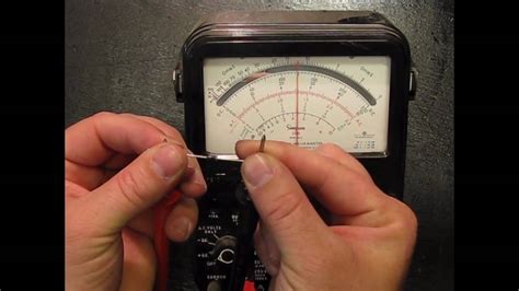
Continuity Test
A continuity test is the simplest way to check if a diode is functioning correctly. This test can be performed using a multimeter with a continuity or diode test function. To perform a continuity test:
- Set your multimeter to the continuity or diode test mode.
- Connect the red probe to the anode (positive side) of the diode and the black probe to the cathode (negative side).
- The multimeter should indicate continuity by displaying a low resistance value or emitting a beep sound.
- Reverse the probe connections and repeat the test. The multimeter should not indicate continuity in this direction.
If the diode passes the continuity test in both directions or fails in both directions, it is likely faulty and should be replaced.
Forward Voltage Drop Test
The forward voltage drop test measures the voltage across the diode when it is conducting current. This test helps determine if the diode is functioning within its specified voltage range. To perform a forward voltage drop test:
- Set your multimeter to the diode test mode or the DC voltage mode with a low range (e.g., 2V or 20V).
- Connect the red probe to the anode and the black probe to the cathode of the diode.
- The multimeter should display the forward voltage drop across the diode, typically between 0.5V and 0.8V for silicon diodes and 0.2V to 0.4V for Schottky diodes.
If the measured voltage drop is significantly higher or lower than the expected value, the diode may be faulty or of a different type than anticipated.
Reverse Leakage Current Test
The reverse leakage current test checks if the diode is blocking current effectively when reverse-biased. To perform this test:
- Set your multimeter to the DC current mode with a high range (e.g., 200mA or 2A).
- Connect the red probe to the cathode and the black probe to the anode of the diode.
- The multimeter should display a very low current, typically in the nanoampere (nA) or microampere (μA) range.
If the measured current is significantly higher than expected, the diode may be faulty or have a high leakage current, which can affect the performance of the circuit.
Dynamic Resistance Test
The dynamic resistance test measures the diode’s resistance when conducting current. This test is particularly useful for matching diodes in parallel or series configurations. To perform a dynamic resistance test:
- Set your multimeter to the resistance mode with a low range (e.g., 200Ω or 2kΩ).
- Connect the probes across the diode in the forward-biased direction (red probe to anode, black probe to cathode).
- The multimeter should display a low resistance value, typically a few ohms for power diodes and tens of ohms for signal diodes.
If the measured resistance is significantly higher or lower than expected, the diode may be faulty or of a different type than anticipated.

Diode Testing Equipment
While a multimeter is sufficient for basic diode testing, more advanced equipment can provide additional insights and capabilities. Some of the specialized diode testing equipment includes:
Curve Tracer
A curve tracer is an instrument that displays the current-voltage (I-V) characteristics of a diode on an oscilloscope screen. It allows you to observe the diode’s behavior under various forward and reverse bias conditions, helping identify issues such as:
- Breakdown voltage
- Reverse leakage current
- Forward voltage drop
- Dynamic resistance
Curve tracers are particularly useful for testing and matching power diodes, Zener diodes, and other specialized diodes.
Semiconductor Analyzer
A semiconductor analyzer is a versatile instrument that can test various semiconductor devices, including diodes, transistors, and thyristors. It provides a range of measurement functions, such as:
- I-V characterization
- Capacitance-voltage (C-V) measurements
- Leakage current measurements
- Breakdown voltage tests
Semiconductor analyzers often have built-in test fixtures and software that simplify the testing process and provide detailed analysis of the device under test.
In-Circuit Tester
An in-circuit tester is a specialized instrument that can test components, including diodes, while they are still connected to the circuit board. It uses a bed-of-nails fixture to make contact with the component leads and performs various tests, such as:
- Continuity
- Resistance
- Capacitance
- Inductance
In-circuit testers are particularly useful for troubleshooting and quality control in manufacturing environments, where testing individual components on a populated circuit board is necessary.
Diode Troubleshooting Tips
When troubleshooting diodes in electronic circuits, keep the following tips in mind:
-
Check the Diode’s Orientation: Ensure that the diode is installed in the correct orientation, with the anode connected to the positive side and the cathode connected to the negative side of the circuit.
-
Verify the Diode’s Specifications: Make sure that the diode’s voltage and current ratings are appropriate for the circuit in which it is used. Using a diode with inadequate ratings can lead to premature failure.
-
Consider the Circuit’s Operating Conditions: Diodes may behave differently under various temperature, frequency, and voltage conditions. Take these factors into account when selecting replacement diodes or troubleshooting issues.
-
Check for Parallel Components: In some circuits, diodes may be connected in parallel with other components, such as capacitors or resistors. These parallel components can affect the diode’s apparent characteristics and should be considered during testing.
-
Use Appropriate Test Equipment: Select the appropriate test equipment based on the diode type and the circuit’s requirements. Using the wrong equipment or test settings can lead to inaccurate results or even damage the diode.
-
Replace Faulty Diodes: If a diode is found to be faulty, replace it with a new one of the same type and rating. Avoid using salvaged or unknown diodes, as they may have hidden defects or incorrect specifications.
Frequently Asked Questions (FAQ)
1. Can a diode be tested without removing it from the circuit?
Yes, diodes can be tested in-circuit using an in-circuit tester or by carefully measuring their forward and reverse characteristics with a multimeter. However, parallel components in the circuit may affect the accuracy of the measurements, so it is often preferable to test diodes individually when possible.
2. How do I identify the anode and cathode of a diode?
The anode of a diode is typically marked with a band or a ‘+’ symbol, while the cathode is usually unmarked or has a ‘-‘ symbol. In some cases, the diode’s packaging may have a diagram indicating the anode and cathode leads.
3. Can a multimeter damage a diode during testing?
In most cases, a multimeter will not damage a diode during testing, as the test current is limited to a safe level. However, using the wrong test settings or applying excessive voltage to the diode can potentially cause damage. Always refer to the multimeter’s manual and the diode’s specifications to ensure safe testing practices.
4. What is the difference between a silicon and a Schottky diode?
Silicon diodes are the most common type and have a forward voltage drop of approximately 0.6V to 0.7V. Schottky diodes, on the other hand, have a lower forward voltage drop (0.2V to 0.4V) and faster switching speeds, making them suitable for high-frequency and low-voltage applications.
5. Can a faulty diode cause other components in the circuit to fail?
Yes, a faulty diode can lead to various issues in the circuit, such as overvoltage, overcurrent, or signal distortion. These issues can stress other components and cause them to fail prematurely. It is essential to identify and replace faulty diodes promptly to prevent cascading failures in the circuit.
Conclusion
Testing diodes is a crucial skill for anyone working with electronic circuits. By understanding the various diode testing methods and using the appropriate equipment, you can quickly identify faulty diodes and troubleshoot issues in your projects. Remember to always handle diodes with care, follow safe testing practices, and replace faulty components with the correct type and rating.
Regular diode testing and maintenance can help ensure the reliability and longevity of your electronic devices, saving you time and money in the long run. With the knowledge gained from this article, you are now better equipped to tackle diode-related issues and keep your circuits functioning optimally.
| Diode Type | Forward Voltage Drop | Reverse Leakage Current | Typical Applications |
|---|---|---|---|
| Rectifier | 0.6V – 0.8V | Low (nA to μA) | Power conversion, signal rectification |
| Zener | Varies (0.2V – 200V) | Very low (nA) | Voltage regulation, reference |
| LED | 1.2V – 3.0V | Very low (nA) | Indication, displays, lighting |
| Schottky | 0.2V – 0.4V | Moderate (μA to mA) | High-frequency, low-voltage switching |
| Varactor | Varies | Low (nA) | Tuning, voltage-controlled capacitance |
No responses yet