Introduction to Flip-Flops
Flip-flops are fundamental building blocks in digital electronics, playing a crucial role in various applications such as data storage, synchronization, and frequency division. They are bistable multivibrator circuits that can store and maintain a binary state (0 or 1) until a specific input condition is met. Flip-flops are widely used in the design of sequential logic circuits, registers, counters, and memory devices.
Types of Flip-Flops
There are several types of flip-flops, each with its unique characteristics and triggering mechanisms:
- SR (Set-Reset) Flip-Flop
- D (Data) Flip-Flop
- JK Flip-Flop
- T (Toggle) Flip-Flop
In this article, we will focus on the negative edge triggered flip-flops, which are a specific type of flip-flop that respond to the falling edge of the clock signal.
Negative Edge Triggered Flip-Flops
Negative edge triggered flip-flops, also known as falling edge triggered flip-flops, are sequential logic circuits that change their output state on the falling edge (transition from high to low) of the clock signal. Unlike positive edge triggered flip-flops, which respond to the rising edge of the clock, negative edge triggered flip-flops are activated when the clock signal transitions from a high level to a low level.
Advantages of Negative Edge Triggered Flip-Flops
-
Reduced Glitches: Negative edge triggered flip-flops can help reduce glitches in the output signal. Glitches are unwanted short pulses that can occur due to signal propagation delays or timing mismatches. By using negative edge triggering, the output changes only on the falling edge of the clock, allowing more time for the input signals to stabilize before the flip-flop captures the data.
-
Improved Timing Margins: Negative edge triggering provides improved timing margins compared to positive edge triggering. Timing margin refers to the amount of time available for the input signals to settle before the flip-flop captures the data. With negative edge triggering, the setup and hold times are referenced to the falling edge of the clock, allowing more time for the input signals to meet the timing requirements.
-
Power Savings: Negative edge triggered flip-flops can contribute to power savings in certain scenarios. When the clock signal is high, the flip-flop is in a stable state, and no transitions occur. By triggering on the falling edge, the flip-flop remains in a stable state for a longer duration, reducing the overall power consumption.
Negative Edge Triggered D Flip-Flop
The negative edge triggered D flip-flop is a commonly used type of flip-flop that captures the input data (D) on the falling edge of the clock signal and presents it at the output (Q). The output remains stable until the next falling edge of the clock.
Truth Table
| D | Clock | Q(next) |
|---|---|---|
| 0 | ↓ | 0 |
| 1 | ↓ | 1 |
| X | 1 or 0 | Q |
In the truth table, ‘↓’ represents the falling edge of the clock, ‘X’ represents a don’t-care condition (either 0 or 1), and ‘Q’ represents the current state of the flip-flop.
Characteristic Equation
The characteristic equation for a negative edge triggered D flip-flop is:
Q(next) = D
This equation indicates that the next state of the output (Q) is equal to the input (D) at the falling edge of the clock.
Timing Diagram
        ___________          ___________
Clock  |           |        |           |
      _|           |________|           |_______
       ___________
D     |           |___________________________
      _____________
Q                 |___________________________
In the timing diagram, the input data (D) is captured on the falling edge of the clock, and the output (Q) changes accordingly.
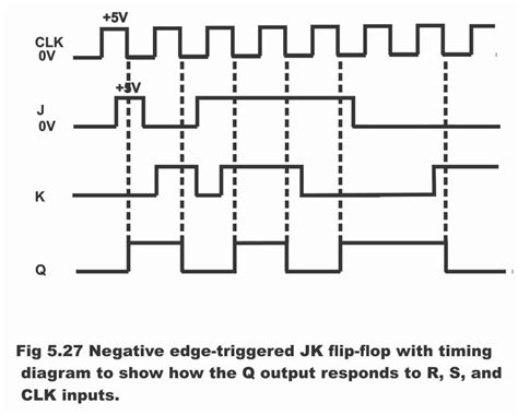
Negative Edge Triggered JK Flip-Flop
The negative edge triggered JK flip-flop is another commonly used type of flip-flop that has two inputs, J (set) and K (reset), and two outputs, Q and Q’ (complement of Q). The JK flip-flop changes its output state based on the values of J and K inputs at the falling edge of the clock.
Truth Table
| J | K | Clock | Q(next) |
|---|---|---|---|
| 0 | 0 | ↓ | Q |
| 0 | 1 | ↓ | 0 |
| 1 | 0 | ↓ | 1 |
| 1 | 1 | ↓ | Q’ |
| X | X | 1 or 0 | Q |
In the truth table, ‘↓’ represents the falling edge of the clock, ‘X’ represents a don’t-care condition (either 0 or 1), ‘Q’ represents the current state of the flip-flop, and ‘Q” represents the complement of the current state.
Characteristic Equation
The characteristic equation for a negative edge triggered JK flip-flop is:
Q(next) = JQ’ + K’Q
This equation indicates that the next state of the output (Q) depends on the current state (Q) and the values of J and K inputs at the falling edge of the clock.
Timing Diagram
        ___________          ___________
Clock  |           |        |           |
      _|           |________|           |_______
       ___________
J     |           |___________________________
       ___________
K     |           |___________________________
      _____________
Q                 |___________________________
      _____________
Q'                |___________________________
In the timing diagram, the J and K inputs are captured on the falling edge of the clock, and the outputs (Q and Q’) change accordingly.

Applications of Negative Edge Triggered Flip-Flops
Negative edge triggered flip-flops find applications in various digital systems and circuits, including:
-
Shift Registers: Negative edge triggered flip-flops are commonly used in shift registers to store and shift data on the falling edge of the clock. Shift registers are used for serial-to-parallel and parallel-to-serial data conversion, data buffering, and delay lines.
-
Counters: Negative edge triggered flip-flops are used in the design of synchronous counters. Counters are sequential circuits that count the number of clock pulses and can be used for frequency division, event counting, and timing control.
-
Frequency Dividers: Negative edge triggered flip-flops can be used to divide the frequency of a clock signal by a specific factor. By cascading multiple flip-flops, different division ratios can be achieved, allowing for the generation of lower frequency signals from a higher frequency clock source.
-
Synchronization Circuits: Negative edge triggered flip-flops are used in synchronization circuits to synchronize asynchronous signals with a clock domain. By capturing the asynchronous signal on the falling edge of the clock, metastability issues can be mitigated, ensuring reliable data transfer between different clock domains.
-
Finite State Machines (FSMs): Negative edge triggered flip-flops are used to implement the state registers in finite state machines. FSMs are sequential circuits that transition between different states based on input conditions and produce outputs accordingly. The flip-flops store the current state of the FSM and update it on the falling edge of the clock.

Advantages and Disadvantages of Negative Edge Triggered Flip-Flops
Advantages
- Reduced glitches and improved signal integrity
- Improved timing margins for setup and hold times
- Potential power savings due to stable state during the high phase of the clock
- Compatibility with systems that require falling edge triggering
Disadvantages
- Increased complexity in clock distribution and timing analysis
- Potential for increased clock skew and jitter
- Limited compatibility with positive edge triggered systems
- Reduced maximum operating frequency compared to positive edge triggered flip-flops

Frequently Asked Questions (FAQs)
-
Q: What is the difference between positive and negative edge triggered flip-flops?
A: Positive edge triggered flip-flops respond to the rising edge (transition from low to high) of the clock signal, while negative edge triggered flip-flops respond to the falling edge (transition from high to low) of the clock signal. -
Q: When should I use negative edge triggered flip-flops?
A: Negative edge triggered flip-flops are preferred when you want to reduce glitches, improve timing margins, or save power in certain scenarios. They are also used when the system requires falling edge triggering or when interfacing with components that operate on the falling edge of the clock. -
Q: Can negative edge triggered flip-flops be used in synchronous designs?
A: Yes, negative edge triggered flip-flops can be used in synchronous designs. They are commonly used in shift registers, counters, frequency dividers, and finite state machines. -
Q: Are there any limitations to using negative edge triggered flip-flops?
A: Negative edge triggered flip-flops may have increased complexity in clock distribution and timing analysis compared to positive edge triggered flip-flops. They may also have reduced maximum operating frequency and limited compatibility with positive edge triggered systems. -
Q: How do I convert a positive edge triggered flip-flop to a negative edge triggered flip-flop?
A: To convert a positive edge triggered flip-flop to a negative edge triggered flip-flop, you can invert the clock signal using an inverter gate. This way, the flip-flop will trigger on the falling edge of the original clock signal.
Conclusion
Negative edge triggered flip-flops are essential components in digital electronics, offering unique advantages such as reduced glitches, improved timing margins, and potential power savings. They are widely used in various applications, including shift registers, counters, frequency dividers, synchronization circuits, and finite state machines.
Understanding the characteristics, truth tables, and timing diagrams of negative edge triggered flip-flops is crucial for designing robust and efficient digital systems. By leveraging the benefits of negative edge triggering, designers can optimize signal integrity, timing, and power consumption in their designs.
However, it is important to consider the trade-offs and limitations associated with negative edge triggered flip-flops, such as increased complexity in clock distribution and timing analysis, reduced maximum operating frequency, and limited compatibility with positive edge triggered systems.
When deciding between positive and negative edge triggering, designers should carefully evaluate the specific requirements and constraints of their system, taking into account factors such as glitch reduction, timing margins, power consumption, and compatibility with other components.
By mastering the concepts and applications of negative edge triggered flip-flops, electronic engineers and hobbyists can enhance their skills in digital circuit design and create more reliable and efficient electronic systems.
No responses yet