What is Opamp Hysteresis?
Operational amplifier (opamp) hysteresis is a technique used to introduce a controlled amount of positive feedback in a circuit to create a bistable output. In other words, it causes the opamp’s output to switch between two stable states based on the input signal level crossing a certain threshold. This hysteresis effect adds noise immunity and prevents unwanted rapid switching of the output due to small fluctuations in the input signal near the threshold point.
Opamp hysteresis is widely used in applications such as:
– Comparator circuits with improved noise immunity
– Schmitt Trigger circuits for generating clean digital signals from noisy or slow-changing inputs
– Level detectors and threshold sensors
– Oscillators and waveform generators
– Debouncing switches and buttons
How Opamp Hysteresis Works
In a basic opamp comparator circuit without hysteresis, the output switches when the input signal crosses the reference voltage. However, if the input signal has noise or slowly changes near the reference level, it can cause the output to rapidly switch back and forth between high and low states. This undesirable behavior is called chattering or oscillation.
To prevent this, hysteresis is introduced by adding positive feedback from the output to the non-inverting input of the opamp. This feedback creates two different threshold voltages: an upper threshold (Vth+) and a lower threshold (Vth-). The output changes state only when the input signal crosses these thresholds, providing a buffer zone where the output remains stable.
The hysteresis voltage (Vhys) is the difference between the upper and lower thresholds:
Vhys = Vth+ – Vth-
The following table summarizes the output states based on the input signal level:
| Input Voltage | Output State |
|---|---|
| Vin < Vth- | Low (0) |
| Vth- < Vin < Vth+ | Previous state retained |
| Vin > Vth+ | High (1) |
The amount of hysteresis can be adjusted by changing the values of the feedback resistors in the circuit.

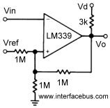
Opamp Hysteresis Circuit Configuration
The most common opamp hysteresis circuit configuration is the non-inverting Schmitt trigger. It consists of an opamp, two resistors (R1 and R2), and a reference voltage (Vref) connected to the inverting input.
Here’s the schematic of a non-inverting Schmitt trigger:
        +Vcc
         |
        +-+
        |  \
        |   \
     R1 |    > R2
        |   /
        |  /
        +-+
         |
Vin -----+-----+
               |
              +-+
              |  \
              |   > Opamp
              |  /
              +-+
               |
               +-----+
               |     |
              Vref  GND
The upper and lower threshold voltages are calculated using the following formulas:
Vth+ = Vref + (R1 / (R1 + R2)) * (Voh – Vref)
Vth- = Vref + (R1 / (R1 + R2)) * (Vol – Vref)
Where:
– Voh is the opamp’s high output voltage (typically close to +Vcc)
– Vol is the opamp’s low output voltage (typically close to GND)
The hysteresis voltage is given by:
Vhys = Vth+ – Vth- = (R1 / (R1 + R2)) * (Voh – Vol)
By selecting appropriate values for R1 and R2, you can set the desired hysteresis voltage and threshold levels.

Designing an Opamp Hysteresis Circuit
When designing an opamp hysteresis circuit, consider the following factors:
-
Hysteresis voltage: Determine the required hysteresis voltage based on the expected noise level and the desired output stability. A larger hysteresis voltage provides better noise immunity but reduces the sensitivity to input changes.
-
Threshold voltages: Choose the upper and lower threshold voltages according to your application requirements. The threshold voltages should be set to detect the desired input signal levels while rejecting noise.
-
Opamp selection: Select an opamp with the appropriate specifications for your application, such as:
- Input offset voltage: Lower offset voltage ensures accurate threshold detection.
- Slew rate: Higher slew rate allows faster output transitions.
- Input impedance: Higher input impedance minimizes loading on the input signal source.
-
Output drive capability: Ensure the opamp can drive the required load current.
-
Feedback resistor values: Calculate the values of R1 and R2 using the hysteresis and threshold voltage formulas. Use standard resistor values closest to the calculated values.
-
Reference voltage: Choose a stable reference voltage source for Vref, such as a voltage divider or a precision voltage reference IC.
-
Power supply decoupling: Provide proper power supply decoupling close to the opamp to minimize noise and ensure stable operation.
-
PCB layout: Follow good PCB layout practices to minimize noise pickup and ensure accurate threshold detection:
- Keep the feedback resistors close to the opamp
- Use ground planes to provide a low-impedance return path
- Separate analog and digital grounds to prevent digital noise from coupling into the analog circuit

Applications of Opamp Hysteresis
Opamp hysteresis finds applications in various domains, including:
- Comparator circuits:
- Window comparators for detecting signal levels within a specific range
- Over-voltage and under-voltage protection circuits
-
Peak detectors and Zero-Crossing Detectors
-
Schmitt triggers:
- Converting noisy or slow-changing inputs into clean digital signals
- Debouncing switches and buttons to prevent multiple triggering
-
Conditioning sensor outputs for reliable digital processing
-
Oscillators and waveform generators:
- Relaxation oscillators using RC or LC networks
- Square wave and triangle wave generators
-
Pulse width modulation (PWM) controllers
-
Level translators:
- Interfacing between different voltage levels (e.g., 3.3V and 5V systems)
-
Providing noise-immune level shifting
-
Analog signal processing:
- Filtering and conditioning low-frequency signals
- Removing glitches and spikes from analog signals
- Implementing hysteretic controllers for power converters
Opamp Hysteresis Design Examples
Here are a few design examples demonstrating the use of opamp hysteresis:
Example 1: Schmitt Trigger with Symmetrical Thresholds
Design a Schmitt trigger circuit with symmetrical thresholds of ±1V using a 5V power supply. The opamp has a high output voltage (Voh) of 4.5V and a low output voltage (Vol) of 0.5V.
Given:
– Vth+ = +1V
– Vth- = -1V
– Vref = 0V (ground)
– Vcc = 5V
– Voh = 4.5V
– Vol = 0.5V
Step 1: Calculate the hysteresis voltage.
Vhys = Vth+ – Vth- = 1V – (-1V) = 2V
Step 2: Choose a value for R2 (e.g., 10kΩ).
Step 3: Calculate the value of R1.
R1 = (Vhys × R2) / (Voh – Vol)
R1 = (2V × 10kΩ) / (4.5V – 0.5V) = 5kΩ
Use standard resistor values of 4.7kΩ for R1 and 10kΩ for R2.
Example 2: Schmitt Trigger with Asymmetrical Thresholds
Design a Schmitt trigger circuit with an upper threshold of 3V and a lower threshold of 1V using a 5V power supply. The opamp has a high output voltage (Voh) of 4.8V and a low output voltage (Vol) of 0.2V.
Given:
– Vth+ = 3V
– Vth- = 1V
– Vref = 2V
– Vcc = 5V
– Voh = 4.8V
– Vol = 0.2V
Step 1: Calculate the hysteresis voltage.
Vhys = Vth+ – Vth- = 3V – 1V = 2V
Step 2: Choose a value for R2 (e.g., 20kΩ).
Step 3: Calculate the value of R1.
R1 = (R2 × (Vth+ – Vref)) / (Vref – Vth-)
R1 = (20kΩ × (3V – 2V)) / (2V – 1V) = 20kΩ
Use standard resistor values of 20kΩ for both R1 and R2.
FAQ
1. What is the purpose of hysteresis in opamp circuits?
Hysteresis in opamp circuits serves the following purposes:
– Provides noise immunity by preventing unwanted output switching due to small input fluctuations near the threshold point.
– Introduces a controlled amount of positive feedback to create a bistable output, ensuring stable switching between two states.
– Helps in generating clean digital signals from noisy or slow-changing inputs.
2. How do I calculate the hysteresis voltage in an opamp Schmitt trigger circuit?
The hysteresis voltage (Vhys) in an opamp Schmitt trigger circuit is the difference between the upper threshold voltage (Vth+) and the lower threshold voltage (Vth-):
Vhys = Vth+ – Vth-
It can also be calculated using the feedback resistor values (R1 and R2) and the opamp’s high and low output voltages (Voh and Vol):
Vhys = (R1 / (R1 + R2)) × (Voh – Vol)
3. What factors should I consider when selecting an opamp for a hysteresis circuit?
When selecting an opamp for a hysteresis circuit, consider the following factors:
– Input offset voltage: Choose an opamp with low offset voltage for accurate threshold detection.
– Slew rate: Ensure the opamp has a high enough slew rate to handle the desired output transition speed.
– Input impedance: Opt for an opamp with high input impedance to minimize loading on the input signal source.
– Output drive capability: Select an opamp that can drive the required load current in your application.
4. How do I set the threshold voltages in an opamp hysteresis circuit?
To set the threshold voltages in an opamp hysteresis circuit:
1. Determine the desired upper (Vth+) and lower (Vth-) threshold voltages based on your application requirements.
2. Choose a reference voltage (Vref) for the inverting input of the opamp, typically set to the midpoint between Vth+ and Vth-.
3. Calculate the values of the feedback resistors (R1 and R2) using the following formulas:
– Vth+ = Vref + (R1 / (R1 + R2)) × (Voh – Vref)
– Vth- = Vref + (R1 / (R1 + R2)) × (Vol – Vref)
4. Select standard resistor values closest to the calculated values for R1 and R2.
5. What are some common applications of opamp hysteresis circuits?
Some common applications of opamp hysteresis circuits include:
– Comparator circuits for detecting signal levels and providing noise immunity
– Schmitt trigger circuits for generating clean digital signals from noisy or slow-changing inputs
– Debouncing switches and buttons to prevent multiple triggering
– Oscillators and waveform generators
– Level translators for interfacing between different voltage levels
– Analog signal processing, such as filtering and conditioning low-frequency signals
By understanding the principles and design considerations of opamp hysteresis, you can effectively implement it in various applications to improve circuit performance and reliability.
No responses yet