Introduction to Schmitt Triggers
A Schmitt trigger is a type of comparator circuit that incorporates positive feedback to achieve hysteresis. Unlike a regular comparator which switches its output when the input crosses a single threshold voltage, a Schmitt trigger uses two different threshold voltages – an upper threshold voltage (VUT) and a lower threshold voltage (VLT). This hysteresis helps to prevent output chattering in noisy environments.
The Schmitt trigger was invented by American scientist Otto H. Schmitt in 1934 while he was a graduate student. It has since found widespread use in a variety of applications including:
- Waveform shaping and noise filtering
- Analog-to-digital converters
- Voltage level detectors
- Oscillator and pulse generator circuits
How a Schmitt Trigger Works
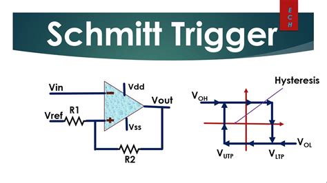
The basic operating principle of a Schmitt trigger is illustrated in the diagram below:
The Schmitt trigger has two key characteristics:
- Two switching thresholds – VUT and VLT
- Hysteresis – the separation between VUT and VLT
When the input voltage (Vin) is below VLT, the output (Vout) is at a logic low level. As Vin rises above VUT, Vout switches to a logic high level. Now as Vin falls, Vout remains high until Vin drops below VLT, at which point it switches back low. This separation between the switching thresholds is called the hysteresis voltage (Vhys).
Vhys = VUT – VLT
The hysteresis voltage makes the Schmitt trigger immune to small voltage fluctuations and noise on the input signal around the threshold points. Without hysteresis, these fluctuations could cause the output to rapidly switch back and forth or “chatter.”
Schmitt Trigger Truth Table
| Vin | Vout (previous state low) | Vout (previous state high) |
|---|---|---|
| <VLT | 0 | 0 |
| >VLT and <VUT | 0 | 1 |
| >VUT | 1 | 1 |
As seen in the truth table, the Schmitt trigger output depends not just on the present input but also on its previous output state, exhibiting hysteresis.

Schmitt Trigger Circuits
Schmitt triggers can be implemented using transistors, op-amps, or dedicated Schmitt trigger logic gates. Let’s look at a few common circuits.
Transistor-Based Schmitt Trigger
A simple Schmitt trigger can be built using two transistors and a few resistors as shown:
In this circuit:
– Q1 and Q2 are NPN bipolar junction transistors
– R1-R4 are resistors that set the threshold voltages
– Vin is the input voltage
– Vout is the output taken from the collector of Q2
The upper and lower threshold voltages are approximately:
VUT ≈ VCC × R3 / (R2 + R3)
VLT ≈ VCC × R4 / (R1 + R4)
Where VCC is the supply voltage.
The hysteresis voltage is:
Vhys ≈ VCC × (R3/(R2+R3) – R4/(R1+R4))
By selecting appropriate resistor values, the threshold voltages can be set as needed for the application.
Op-Amp Schmitt Trigger
An op-amp Schmitt trigger uses positive feedback from the output back to the non-inverting input to create hysteresis:
The threshold voltages for an op-amp Schmitt trigger are given by:
VUT = VOH × R1 / (R1 + R2)
VLT = VOL × R1 / (R1 + R2)
Where:
– VOH is the op-amp’s high output voltage level
– VOL is the op-amp’s low output voltage level
And the hysteresis voltage is:
Vhys = (VOH – VOL) × R1 / (R1 + R2)
Op-amp Schmitt triggers provide very precise thresholds and high noise immunity. Dedicated Schmitt trigger op-amps are also available which include the hysteresis-setting resistors internally.
CMOS Schmitt Trigger Gates
Many logic families include Schmitt trigger gates that have the hysteresis built in. For example, the 74HC14 hex inverting Schmitt trigger:
This IC contains six independent inverting Schmitt triggers in a single package. The hysteresis levels are internally set. CMOS Schmitt triggers have the advantage of low power consumption, high noise immunity, and direct compatibility with logic-level signals.

Applications of Schmitt Triggers
Waveform Shaping and Noise Filtering
One of the most common uses of Schmitt triggers is to clean up noisy and slowly changing input signals into clean, fast-switching digital waveforms.
As seen in the animation, a slowly varying input with noise is converted into a clean, sharp-edged digital signal by the Schmitt trigger. The hysteresis prevents multiple output transitions due to noise.
Voltage Level Detection
Schmitt triggers make excellent voltage level detectors. By setting the threshold voltages appropriately, a Schmitt trigger can detect when a voltage crosses a certain level and provide a clean digital output.
For example, a battery voltage monitor could use a Schmitt trigger to signal when the voltage drops below a minimum level:
Oscillator Circuits
The hysteresis of a Schmitt trigger can be used to build simple oscillator circuits. By connecting a capacitor and resistor to a Schmitt trigger in a feedback configuration, the circuit will oscillate.
Here’s a simple Schmitt trigger oscillator:
The frequency of oscillation is approximately:
f ≈ 1 / (2 × R × C × ln((VUT / VLT))
Where:
– R and C are the resistor and capacitor values
– VUT and VLT are the Schmitt trigger thresholds
This type of relaxation oscillator is simple to build but not highly precise in frequency. For more precise oscillators, crystal, ceramic resonator, or RC active oscillator circuits are used.

Schmitt Trigger FAQs
Q1: What is the main advantage of a Schmitt trigger over a regular comparator?
A1: The main advantage is the built-in hysteresis which provides immunity to noise and input signal fluctuations around the switching point. This prevents output chatter and provides a clean digital output.
Q2: Can a Schmitt trigger be used as an analog-to-digital converter?
A2: Yes, a Schmitt trigger can be used as a simple 1-bit ADC. By comparing an analog input to the Schmitt trigger thresholds, a digital high or low output is produced. However, for multi-bit ADCs, more sophisticated circuits like successive approximation or flash ADCs are used.
Q3: What determines the hysteresis voltage of a Schmitt trigger?
A3: The hysteresis voltage is determined by the circuit component values, usually resistors, that set the upper and lower threshold voltages. In a transistor Schmitt trigger, the emitter and collector resistor ratios set the thresholds. In an op-amp Schmitt trigger, the feedback resistor ratio sets the hysteresis.
Q4: Are Schmitt triggers available as integrated circuits?
A4: Yes, Schmitt triggers are available as dedicated ICs in both logic gate (e.g. 74HC14) and op-amp (e.g. LM393) forms. These ICs have the hysteresis levels internally set and offer high performance and convenience.
Q5: What are some common applications of Schmitt triggers?
A5: Schmitt triggers are widely used for:
– Cleaning up noisy and slowly changing input signals into clean digital waveforms
– Detecting when a voltage crosses a certain level (voltage level detectors)
– Building simple oscillator circuits
– Providing hysteresis in control systems to prevent rapid switching around a setpoint
Conclusion
The Schmitt trigger is a versatile and widely used circuit that provides a clean, fast digital output from a noisy or slowly varying input signal. By incorporating hysteresis using two switching thresholds, Schmitt triggers offer excellent noise immunity and output stability.
Available in transistor, op-amp, and logic gate implementations, Schmitt triggers find use in a broad range of applications from signal conditioning to oscillators and level detectors. Understanding the operation and uses of Schmitt triggers is valuable for any electronics engineer or hobbyist.
No responses yet