Introduction to Zener Diodes and the 1N4732A
A Zener diode is a special type of diode that allows current to flow in the forward direction like a normal diode, but also in the reverse direction if the voltage is larger than the rated breakdown voltage known as the “Zener voltage”. The device maintains a nearly constant voltage in the reverse direction when conducting reverse current. This makes Zener diodes useful as voltage references and for voltage regulation.
The 1N4732A is a popular Zener diode with a Zener voltage of 4.7 V. In this comprehensive guide, we’ll cover everything you need to know about the 1N4732A Zener diode, including its specifications, applications, and circuit design considerations.
1N4732A Specifications
Let’s start by examining the key specifications of the 1N4732A Zener diode:
| Parameter | Value |
|---|---|
| Zener Voltage (VZ) | 4.7 V ± 5% @ IZT = 41 mA |
| Maximum Power Dissipation (PD) | 1 W |
| Maximum Reverse Current (IR) | 100 μA @ VR = 1 V |
| Operating Temperature Range | -65°C to +200°C |
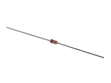
| Package | DO-41 (Axial Leaded) |
The 1N4732A has a nominal Zener voltage of 4.7 V with a tolerance of ±5% when the Zener test current (IZT) is 41 mA. This means that the actual Zener voltage can range from 4.465 V to 4.935 V under these conditions.
The maximum power dissipation of the 1N4732A is 1 W, which indicates the highest power the device can safely handle without damage. It’s essential to ensure that the power dissipated by the Zener diode does not exceed this limit in your circuit design.
The maximum reverse current (IR) is specified as 100 μA when the reverse voltage (VR) is 1 V. This low leakage current is important for applications where the Zener diode is used as a voltage reference.
The 1N4732A can operate over a wide temperature range from -65°C to +200°C, making it suitable for various environments.

How Zener Diodes Work
To understand how Zener diodes work, let’s look at their current-voltage (I-V) characteristic curve:
[Include an image of a typical Zener diode I-V curve]
In the forward direction (positive voltage applied to the anode), the Zener diode behaves like a normal diode, allowing current to flow when the forward voltage exceeds the diode’s threshold voltage (typically 0.6-0.7 V for silicon diodes).
However, in the reverse direction (negative voltage applied to the anode), the Zener diode exhibits a unique behavior. When the reverse voltage is below the Zener voltage (VZ), only a small leakage current flows through the diode. But when the reverse voltage reaches or exceeds VZ, the diode starts conducting a significant amount of reverse current while maintaining a nearly constant voltage drop equal to VZ. This voltage regulation property is the key feature of Zener diodes.
The Zener breakdown occurs due to two mechanisms:
-
Zener Breakdown: At lower reverse voltages, the strong electric field across the depletion region causes electrons to tunnel directly from the valence band to the conduction band, resulting in a sudden increase in reverse current. This quantum mechanical tunneling effect is called Zener breakdown.
-
Avalanche Breakdown: At higher reverse voltages, the electric field accelerates free electrons to high velocities, causing them to collide with the lattice and generate additional electron-hole pairs. These newly generated carriers are also accelerated and create more electron-hole pairs, leading to a rapid increase in reverse current. This process is called avalanche breakdown.
In practice, both Zener and avalanche breakdowns contribute to the overall breakdown mechanism in a Zener diode, with the dominant effect depending on the doping levels and the Zener voltage.

Applications of the 1N4732A Zener Diode
The 1N4732A Zener diode finds applications in various circuits where a stable 4.7 V reference voltage or voltage regulation is required. Some common applications include:
Voltage Reference
One of the primary uses of the 1N4732A is as a voltage reference in analog circuits, such as ADCs, DACs, and voltage regulators. By connecting the Zener diode in reverse bias with a current-limiting resistor, you can create a stable 4.7 V reference voltage across the diode.
[Include a schematic of a basic Zener diode voltage reference circuit]
Voltage Regulation
The 1N4732A can also be used as a simple voltage regulator to maintain a constant 4.7 V output voltage from a higher input voltage. The Zener diode is connected in parallel with the load, and a series resistor is used to limit the current through the diode.
[Include a schematic of a basic Zener diode voltage regulator circuit]
Overvoltage Protection
Zener diodes can be used to protect sensitive electronic components from overvoltage conditions. By connecting the 1N4732A in parallel with the component to be protected, the Zener diode will clamp the voltage across the component to 4.7 V, preventing damage from excessive voltages.
[Include a schematic of an overvoltage protection circuit using a Zener diode]
Voltage Clamping
The 1N4732A can be used to clamp AC voltages to a maximum of 4.7 V peak. This is useful in applications where you need to limit the amplitude of an AC signal, such as in waveform generators or signal conditioning circuits.
[Include a schematic of a Zener diode voltage clamping circuit]

Designing with the 1N4732A Zener Diode
When designing circuits using the 1N4732A Zener diode, there are several important factors to consider:
Power Dissipation
Ensure that the power dissipated by the Zener diode does not exceed its maximum power dissipation rating of 1 W. The power dissipated by the Zener diode can be calculated using the formula:
PZ = VZ × IZ
Where:
– PZ is the power dissipated by the Zener diode
– VZ is the Zener voltage (4.7 V for the 1N4732A)
– IZ is the current through the Zener diode
If the power dissipation exceeds 1 W, you may need to use a heat sink or a Zener diode with a higher power rating.
Temperature Effects
The Zener voltage of the 1N4732A has a negative temperature coefficient, which means that the Zener voltage decreases slightly with increasing temperature. The temperature coefficient is typically around -2 mV/°C. Keep this in mind when designing for applications that operate over a wide temperature range.
Noise and Ripple
Zener diodes generate electrical noise due to the breakdown mechanism. This noise can be minimized by adding a capacitor in parallel with the Zener diode to filter out high-frequency noise components. The capacitor value should be chosen based on the desired noise reduction and the circuit’s operating frequency.
Current Limiting Resistor Selection
When using the 1N4732A in a voltage reference or regulator circuit, it’s essential to select an appropriate current-limiting resistor. The resistor value should be chosen to ensure that the current through the Zener diode is within the device’s specifications while also considering the desired load current.
The current-limiting resistor value can be calculated using the formula:
R = (Vin – VZ) / (IZ + Iload)
Where:
– R is the current-limiting resistor value
– Vin is the input voltage
– VZ is the Zener voltage (4.7 V for the 1N4732A)
– IZ is the desired Zener current (typically a few mA to a few tens of mA)
– Iload is the load current
Frequently Asked Questions (FAQ)
1. What is the difference between a Zener diode and a regular diode?
A Zener diode is designed to allow current to flow in the reverse direction when the reverse voltage exceeds the Zener voltage, while maintaining a nearly constant voltage drop. A regular diode only allows current to flow in the forward direction and has a fixed forward voltage drop.
2. Can I use the 1N4732A Zener diode for overvoltage protection in my circuit?
Yes, the 1N4732A can be used for overvoltage protection by connecting it in parallel with the component you want to protect. When the voltage across the component exceeds 4.7 V, the Zener diode will start conducting and clamp the voltage to protect the component.
3. How much power can the 1N4732A Zener diode dissipate?
The 1N4732A has a maximum power dissipation rating of 1 W. Make sure that the power dissipated by the Zener diode in your circuit does not exceed this value, or the device may be damaged.
4. What happens if I use a Zener diode with a higher Zener voltage than the 1N4732A in my circuit?
If you use a Zener diode with a higher Zener voltage, the regulated voltage in your circuit will be higher. For example, if you use a 1N4733A (5.1 V Zener voltage) instead of a 1N4732A (4.7 V Zener voltage), the regulated voltage will be 5.1 V instead of 4.7 V.
5. Can I connect multiple 1N4732A Zener diodes in series to obtain a higher regulated voltage?
Yes, you can connect multiple 1N4732A Zener diodes in series to obtain a higher regulated voltage. The resulting regulated voltage will be the sum of the individual Zener voltages. However, keep in mind that the power dissipation will also increase, so make sure to choose appropriate current-limiting resistors and consider the total power dissipation of the series-connected diodes.
Conclusion
The 1N4732A Zener diode is a versatile and widely used device for voltage referencing, regulation, overvoltage protection, and clamping. By understanding its specifications, working principles, and design considerations, you can effectively incorporate the 1N4732A into your electronic circuits.
Remember to consider factors such as power dissipation, temperature effects, noise, and ripple when designing with Zener diodes. Proper selection of the current-limiting resistor is also crucial for optimal performance.
This comprehensive guide has covered everything you need to know about the 1N4732A Zener diode. For more information on Zener diodes and their applications, consult datasheets, application notes, and reference designs from semiconductor manufacturers.
No responses yet