Introduction to NodeMCU
NodeMCU is an open-source firmware and development board that is widely used for IoT (Internet of Things) projects. It is based on the ESP8266 Wi-Fi SoC (System on Chip) and uses the Lua scripting language for programming. NodeMCU provides an easy-to-use and cost-effective platform for building connected devices and applications.
What is NodeMCU?
NodeMCU is a combination of hardware and software that enables developers to create IoT projects quickly and efficiently. The hardware component is a development board that integrates the ESP8266 Wi-Fi module, while the software component is an open-source firmware that runs on the board.
The NodeMCU firmware is built on top of the ESP8266 SDK (Software Development Kit) and provides a simple and intuitive way to program the board using Lua scripts. Lua is a lightweight scripting language that is easy to learn and has a small memory footprint, making it suitable for resource-constrained devices like the ESP8266.
Advantages of using NodeMCU
There are several advantages to using NodeMCU for IoT projects:
-
Cost-effective: NodeMCU boards are relatively inexpensive compared to other development boards, making them accessible to a wide range of developers and hobbyists.
-
Easy to use: The NodeMCU firmware provides a simple and intuitive programming interface that allows developers to quickly prototype and build IoT applications.
-
Wi-Fi connectivity: The ESP8266 module integrated into the NodeMCU board provides built-in Wi-Fi connectivity, enabling devices to connect to the internet and communicate with other devices.
-
Large community support: NodeMCU has a large and active community of developers who contribute to the project and provide support through forums, tutorials, and libraries.
NodeMCU Pinout
To effectively use the NodeMCU board for your projects, it is essential to understand its pinout and the functionality of each pin. In this section, we will explore the NodeMCU pinout in detail.
NodeMCU Development Board
The NodeMCU development board comes in various versions, with the most common being the NodeMCU V3 (also known as NodeMCU 1.0). The board features the ESP8266 Wi-Fi module, a USB-to-Serial converter, and a voltage regulator.
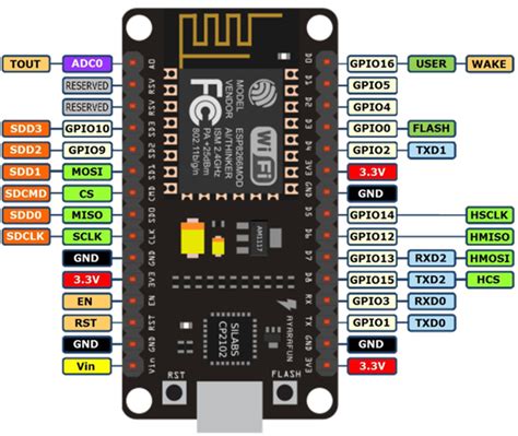
NodeMCU Pinout Diagram
Here is a pinout diagram for the NodeMCU V3 board:
Pin Functions
Let’s take a closer look at the functions of each pin on the NodeMCU board:
| Pin | Function | Description |
|---|---|---|
| VIN | Input Voltage | This pin is used to supply power to the board when not using USB. The input voltage range is 4.75V to 10V. |
| GND | Ground | Ground pin for power supply and other connections. |
| 3.3V | 3.3V Power Supply | This pin provides a regulated 3.3V output that can be used to power external components. |
| RST | Reset | This pin is used to reset the ESP8266 module. It is active-low, meaning that pulling it to ground will reset the module. |
| A0 | Analog Input | This pin is used for analog input and can measure voltages between 0V and 3.3V. |
| D0-D8 | Digital Input/Output | These pins can be used for digital input or output. They are also used for PWM (Pulse Width Modulation) and communication protocols like I2C and SPI. |
| D9, D10 | Digital Input/Output | These pins are used for digital input or output but do not support PWM, I2C or SPI. |
| SD1, SD2, SD3 | SPI Chip Select | These pins are used as chip select pins for SPI communication. |
| CLK | SPI Clock | This pin is used as the clock signal for SPI communication. |
| CMD | SPI Command | This pin is used to send commands during SPI communication. |
| RXD0 | UART0 Receive | This pin is used for UART0 serial communication to receive data. |
| TXD0 | UART0 Transmit | This pin is used for UART0 serial communication to transmit data. |

Setting Up NodeMCU
To start using NodeMCU for your projects, you need to set up the development environment and flash the firmware onto the board. In this section, we will guide you through the process of setting up NodeMCU.
Installing the USB Driver
Before you can connect the NodeMCU board to your computer, you need to install the appropriate USB driver. The NodeMCU board uses the CH340G USB-to-Serial converter, which requires a specific driver.
- Download the CH340G driver from the official website or a trusted source.
- Install the driver on your computer by following the provided instructions.
- Once the installation is complete, connect the NodeMCU board to your computer using a USB cable.
Installing the Arduino IDE
The Arduino IDE (Integrated Development Environment) is a popular choice for programming NodeMCU boards. Follow these steps to install the Arduino IDE:
- Download the Arduino IDE from the official website: https://www.arduino.cc/en/software
- Install the Arduino IDE on your computer by following the provided instructions.
Adding NodeMCU Board to Arduino IDE
To program the NodeMCU board using the Arduino IDE, you need to add the NodeMCU board package to the IDE:
- Open the Arduino IDE.
- Go to File > Preferences.
- In the “Additional Boards Manager URLs” field, enter the following URL:
http://arduino.esp8266.com/stable/package_esp8266com_index.json - Click “OK” to close the Preferences window.
- Go to Tools > Board > Boards Manager.
- Search for “esp8266” in the search bar.
- Click on the “esp8266” package and select the latest version.
- Click “Install” and wait for the installation to complete.
Flashing the NodeMCU Firmware
To use the NodeMCU board with the Arduino IDE, you need to flash the firmware onto the board. Follow these steps:
- Download the latest version of the NodeMCU firmware from the official repository: https://github.com/nodemcu/nodemcu-firmware/releases
- Connect the NodeMCU board to your computer using a USB cable.
- Open the Arduino IDE.
- Go to Tools > Board and select “NodeMCU 1.0 (ESP-12E Module)” from the list.
- Go to Tools > Port and select the COM port that corresponds to your NodeMCU board.
- Open the NodeMCU firmware file in the Arduino IDE.
- Click the “Upload” button to flash the firmware onto the board.

Programming NodeMCU
With the NodeMCU board set up and the firmware flashed, you are now ready to start programming your IoT projects. In this section, we will cover the basics of programming NodeMCU using the Arduino IDE and Lua scripts.
Arduino IDE Programming
The Arduino IDE provides a familiar environment for programming the NodeMCU board using C++. Here’s a simple example that blinks the onboard LED:
#define LED_PIN D4

void setup() {
  pinMode(LED_PIN, OUTPUT);
}

void loop() {
  digitalWrite(LED_PIN, HIGH);
  delay(1000);
  digitalWrite(LED_PIN, LOW);
  delay(1000);
}
In this example:
1. We define the LED_PIN constant to specify the pin connected to the onboard LED (D4 in this case).
2. In the setup() function, we set the LED_PIN as an output using pinMode().
3. In the loop() function, we turn the LED on by setting the LED_PIN to HIGH, wait for 1 second using delay(1000), then turn the LED off by setting the LED_PIN to LOW, and wait for another second.
To upload this sketch to the NodeMCU board:
1. Copy the code into a new sketch in the Arduino IDE.
2. Make sure the NodeMCU board is selected in Tools > Board.
3. Select the correct COM port in Tools > Port.
4. Click the “Upload” button to compile and upload the sketch to the board.
Lua Programming
NodeMCU firmware also supports programming using Lua scripts. Lua is a lightweight scripting language that is well-suited for embedded devices. Here’s an example of a Lua script that blinks the onboard LED:
local pin = 4
gpio.mode(pin, gpio.OUTPUT)

tmr.create():alarm(1000, tmr.ALARM_AUTO, function()
  if gpio.read(pin) == 0 then
    gpio.write(pin, 1)
  else
    gpio.write(pin, 0)
  end
end)
In this example:
1. We define the pin variable to specify the GPIO pin connected to the onboard LED (GPIO 4, which corresponds to D4).
2. We set the pin mode to gpio.OUTPUT using gpio.mode().
3. We create a timer using tmr.create() that triggers every 1000 milliseconds (1 second) and toggles the state of the LED using gpio.write().
To run this Lua script on the NodeMCU board:
1. Connect the NodeMCU board to your computer using a USB cable.
2. Use a serial terminal program (e.g., PuTTY, Arduino IDE Serial Monitor) to connect to the board.
3. Copy the Lua script and paste it into the serial terminal.
4. Press Enter to execute the script.

NodeMCU Projects and Examples
Now that you have a basic understanding of the NodeMCU pinout and programming, let’s explore some practical projects and examples that demonstrate the capabilities of this versatile development board.
Project 1: Web Server
One of the most common applications of NodeMCU is creating a web server that can be accessed over Wi-Fi. In this example, we will create a simple web server that allows you to control an LED connected to the NodeMCU board.
#include <ESP8266WiFi.h>

const char* ssid = "YourWiFiSSID";
const char* password = "YourWiFiPassword";

WiFiServer server(80);

#define LED_PIN D4

void setup() {
  Serial.begin(115200);
  pinMode(LED_PIN, OUTPUT);

  WiFi.begin(ssid, password);
  while (WiFi.status() != WL_CONNECTED) {
    delay(1000);
    Serial.println("Connecting to WiFi...");
  }

  Serial.println("WiFi connected!");
  Serial.println(WiFi.localIP());

  server.begin();
}

void loop() {
  WiFiClient client = server.available();
  if (client) {
    String request = client.readStringUntil('\r');
    client.flush();

    if (request.indexOf("/LED=ON") != -1) {
      digitalWrite(LED_PIN, HIGH);
    } else if (request.indexOf("/LED=OFF") != -1) {
      digitalWrite(LED_PIN, LOW);
    }

    client.println("HTTP/1.1 200 OK");
    client.println("Content-Type: text/html");
    client.println("");
    client.println("<!DOCTYPE HTML>");
    client.println("<html>");
    client.println("<h1>NodeMCU Web Server</h1>");
    client.println("<p>LED Control:</p>");
    client.println("<a href=\"/LED=ON\"><button>ON</button></a>");
    client.println("<a href=\"/LED=OFF\"><button>OFF</button></a>");
    client.println("</html>");
    client.stop();
  }
}
In this example:
1. We include the ESP8266WiFi.h library to enable Wi-Fi functionality.
2. We define the Wi-Fi SSID and password to connect to your network.
3. We create a WiFiServer object on port 80 to handle HTTP requests.
4. In the setup() function, we initialize the serial communication, set the LED pin as an output, connect to Wi-Fi, and start the server.
5. In the loop() function, we check for incoming client requests and process them accordingly. If the request contains “/LED=ON”, we turn the LED on, and if it contains “/LED=OFF”, we turn the LED off.
6. We send an HTML response to the client with buttons to control the LED state.
Upload this sketch to your NodeMCU board, and once it connects to Wi-Fi, you can access the web server by entering the IP address displayed in the serial monitor into a web browser. You should see a simple web page with buttons to control the LED connected to the NodeMCU board.
Project 2: MQTT Client
MQTT (Message Queuing Telemetry Transport) is a lightweight publish-subscribe protocol commonly used in IoT applications. In this example, we will create an MQTT client that publishes sensor data to a broker and subscribes to a topic to control an LED.
#include <ESP8266WiFi.h>
#include <PubSubClient.h>

const char* ssid = "YourWiFiSSID";
const char* password = "YourWiFiPassword";
const char* mqtt_server = "broker.hivemq.com";

WiFiClient espClient;
PubSubClient client(espClient);

#define LED_PIN D4
#define SENSOR_PIN A0

void setup() {
  Serial.begin(115200);
  pinMode(LED_PIN, OUTPUT);
  pinMode(SENSOR_PIN, INPUT);

  WiFi.begin(ssid, password);
  while (WiFi.status() != WL_CONNECTED) {
    delay(1000);
    Serial.println("Connecting to WiFi...");
  }

  Serial.println("WiFi connected!");

  client.setServer(mqtt_server, 1883);
  client.setCallback(callback);
}

void loop() {
  if (!client.connected()) {
    reconnect();
  }
  client.loop();

  int sensorValue = analogRead(SENSOR_PIN);
  char payload[10];
  snprintf(payload, sizeof(payload), "%d", sensorValue);
  client.publish("nodemcu/sensor", payload);

  delay(5000);
}

void callback(char* topic, byte* payload, unsigned int length) {
  if (strcmp(topic, "nodemcu/led") == 0) {
    if (payload[0] == '1') {
      digitalWrite(LED_PIN, HIGH);
    } else {
      digitalWrite(LED_PIN, LOW);
    }
  }
}

void reconnect() {
  while (!client.connected()) {
    Serial.println("Connecting to MQTT broker...");
    if (client.connect("NodeMCUClient")) {
      Serial.println("Connected to MQTT broker");
      client.subscribe("nodemcu/led");
    } else {
      Serial.print("Failed, rc=");
      Serial.print(client.state());
      Serial.println(" retrying in 5 seconds");
      delay(5000);
    }
  }
}
In this example:
1. We include the ESP8266WiFi.h and PubSubClient.h libraries for Wi-Fi and MQTT functionality.
2. We define the Wi-Fi SSID, password, and MQTT broker details.
3. We create a WiFiClient and PubSubClient object to handle the MQTT connection.
4. In the setup() function, we initialize the serial communication, set the LED and sensor pins, connect to Wi-Fi, and set up the MQTT client.
5. In the loop() function, we check the MQTT connection and reconnect if necessary. We read the sensor value and publish it to the “nodemcu/sensor” topic every 5 seconds.
6. The callback() function is called whenever a message is received on a subscribed topic. If the message is “1” on the “nodemcu/led” topic, we turn the LED on, otherwise, we turn it off.
7. The reconnect() function handles the MQTT connection and subscribes to the “nodemcu/led” topic.
Upload this sketch to your NodeMCU board, and it will connect to the specified MQTT broker. You can use an MQTT client like MQTT.fx or the mosquitto
No responses yet