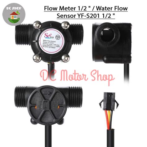
What is the YF-s201 Water Sensor?
The YF-s201 is a hall effect-based water flow sensor designed to measure the flow rate of liquids in pipes and tubes. It consists of a plastic valve body, a water rotor, and a Hall Effect Sensor. As water flows through the valve, it causes the rotor to spin, and the hall effect sensor detects the rotation, generating pulses that can be used to calculate the flow rate.
Key Features of the YF-s201 Water Sensor
- Hall effect sensing for accurate flow rate measurement
- Compact and lightweight design for easy installation
- Wide operating voltage range (5-24V DC)
- Low power consumption
- Durable plastic construction
- 1/2″ NPT threaded connections for standard pipe fittings
- Flow rate range: 1-30 L/min
- Maximum water pressure: 2.0 MPa
- Operating temperature range: 0°C to 80°C
YF-s201 Pinout and Wiring
The YF-s201 water sensor has three pins for easy integration with microcontrollers, such as Arduino or Raspberry Pi.
| Pin | Function | Wire Color |
|---|---|---|
| 1 | VCC (5-24V DC) | Red |
| 2 | GND | Black |
| 3 | Signal Output | Yellow |
To connect the YF-s201 to a microcontroller, follow these steps:
- Connect the red wire (VCC) to a 5-24V DC power source.
- Connect the black wire (GND) to the ground of the power source and microcontroller.
- Connect the yellow wire (Signal Output) to a digital input pin on the microcontroller.

How the YF-s201 Water Sensor Works
The YF-s201 water sensor uses the hall effect principle to measure the flow rate of liquids. The sensor consists of three main components:
- Plastic valve body: Houses the rotor and guides the liquid flow.
- Water rotor: Spins as the liquid flows through the valve.
- Hall effect sensor: Detects the rotation of the rotor and generates pulses.
As liquid flows through the valve body, it causes the rotor to spin. The hall effect sensor, positioned near the rotor, detects the magnetic field changes caused by the spinning rotor. Each time a rotor blade passes the sensor, it generates a pulse. By counting the number of pulses within a specific time interval, the flow rate can be calculated.
The YF-s201 generates approximately 450 pulses per liter of liquid. To calculate the flow rate, use the following formula:
Flow Rate (L/min) = (Pulse Frequency (Hz) * 60) / 450

Calibrating the YF-s201 Water Sensor
To ensure accurate flow rate measurements, it is essential to calibrate the YF-s201 water sensor. The calibration process involves determining the exact number of pulses generated per liter of liquid for your specific setup. Follow these steps to calibrate the sensor:
-
Connect the YF-s201 to a microcontroller and upload a sketch that counts the pulses generated by the sensor over a fixed time interval (e.g., 1 minute).
-
Prepare a container with a known volume (e.g., 1 liter) and place it at the outlet of the sensor.
-
Start the water flow and simultaneously start the pulse counting sketch on the microcontroller.
-
Allow the water to flow until the container is filled to the known volume, then stop the water flow and the pulse counting sketch.
-
Record the number of pulses counted during the calibration process.
-
Calculate the calibration factor using the following formula:
Calibration Factor (pulses/L) = Pulses Counted / Known Volume (L) -
Update the flow rate calculation formula in your sketch with the new calibration factor:
Flow Rate (L/min) = (Pulse Frequency (Hz) * 60) / Calibration Factor

Applications of the YF-s201 Water Sensor
The YF-s201 water sensor’s versatility and reliability make it suitable for a wide range of applications, including:
- Home automation:
- Monitoring water consumption in smart homes
- Detecting leaks in pipes and appliances
-
Controlling irrigation systems
-
Industrial processes:
- Monitoring coolant flow in machining operations
- Measuring the flow of chemicals in processing plants
-
Controlling the flow of liquids in food and beverage production
-
Agricultural monitoring:
- Measuring irrigation water usage
- Optimizing fertigation systems
-
Detecting leaks in irrigation pipelines
-
Environmental monitoring:
- Measuring water flow in rivers and streams
- Monitoring groundwater extraction rates
-
Detecting changes in water flow patterns
-
Research and education:
- Conducting experiments involving fluid dynamics
- Demonstrating the principles of flow measurement
- Developing sensor-based projects for STEM education
Sample Arduino Code for the YF-s201 Water Sensor
Here’s a simple Arduino sketch that demonstrates how to read the pulse output from the YF-s201 water sensor and calculate the flow rate:
const int sensorPin = 2;
const float calibrationFactor = 450; // Adjust this value based on your calibration

volatile int pulseCount = 0;
float flowRate = 0.0;
unsigned long lastTime = 0;

void setup() {
  Serial.begin(9600);
  pinMode(sensorPin, INPUT);
  attachInterrupt(digitalPinToInterrupt(sensorPin), pulseCounter, FALLING);
}

void loop() {
  if (millis() - lastTime > 1000) {
    detachInterrupt(digitalPinToInterrupt(sensorPin));
    flowRate = (pulseCount * 60.0) / calibrationFactor;
    pulseCount = 0;
    attachInterrupt(digitalPinToInterrupt(sensorPin), pulseCounter, FALLING);
    lastTime = millis();

    Serial.print("Flow Rate: ");
    Serial.print(flowRate);
    Serial.println(" L/min");
  }
}

void pulseCounter() {
  pulseCount++;
}
This sketch uses the attachInterrupt() function to count the pulses generated by the YF-s201 water sensor. The pulse count is then used to calculate the flow rate every second, and the result is displayed on the serial monitor.
Frequently Asked Questions (FAQ)
-
What is the maximum flow rate that the YF-s201 can measure?
The YF-s201 water sensor can measure flow rates up to 30 L/min (8 GPM). -
Is the YF-s201 water sensor compatible with both 3.3V and 5V microcontrollers?
Yes, the YF-s201 can work with both 3.3V and 5V microcontrollers, as long as the supplied voltage is within the sensor’s operating range of 5-24V DC. -
Can the YF-s201 water sensor be used with liquids other than water?
While the YF-s201 is primarily designed for use with water, it can be used with other non-corrosive liquids that have similar viscosity to water. However, the calibration factor may need to be adjusted for accurate flow rate measurements. -
How do I install the YF-s201 water sensor in a pipe system?
The YF-s201 has 1/2″ NPT threaded connections on both ends, which are compatible with standard pipe fittings. To install the sensor, use appropriate adapters or unions to connect it to your pipe system, ensuring that the flow direction arrow on the sensor body matches the actual flow direction. -
What should I do if the YF-s201 water sensor is not providing accurate readings?
If the YF-s201 is not providing accurate readings, first check the wiring connections to ensure they are secure and correct. If the wiring is correct, recalibrate the sensor using the process described in the “Calibrating the YF-s201 Water Sensor” section of this article. If the issue persists, check for any debris or obstructions in the sensor body that may be interfering with the rotor’s rotation.
Conclusion
The YF-s201 Hall Effect water sensor is a reliable and cost-effective solution for measuring liquid flow rates in various applications. Its compact size, easy installation, and compatibility with standard pipe fittings make it an attractive choice for both hobbyists and professionals alike. By understanding the sensor’s pinout, features, and calibration process, users can effectively integrate the YF-s201 into their projects and achieve accurate flow rate measurements.
No responses yet