What is the ACS712 Current Sensor?
The ACS712 is a Hall Effect-based linear current sensor IC. It is designed to measure both AC and DC currents and provides electrical isolation between the measured current and the output signal. The sensor comes in different current ranges, making it suitable for a wide range of applications.
Key Features of the ACS712 Current Sensor
- Measures both AC and DC currents
- Available in different current ranges: ±5A, ±20A, ±30A
- Provides electrical isolation between the measured current and the output signal
- Low-noise analog signal output
- Wide operating voltage range: 5V to 12V
- Compact and easy to integrate into projects
How Does the ACS712 Current Sensor Work?
The ACS712 current sensor utilizes the Hall Effect principle to measure the current flowing through a conductor. It consists of a Hall Effect Sensor, a copper conduction path, and signal conditioning circuitry integrated into a single package.
Hall Effect Principle
The Hall Effect is a phenomenon where a voltage difference is generated across a conductor when a magnetic field is applied perpendicular to the current flow. In the ACS712 sensor, the magnetic field is generated by the current flowing through the copper conduction path. The Hall Effect sensor detects this magnetic field and generates a proportional voltage output.
Current Measurement
The current to be measured is passed through the copper conduction path of the ACS712 sensor. As the current flows, it generates a magnetic field around the conductor. The Hall Effect sensor, which is placed in close proximity to the conductor, detects this magnetic field and generates an output voltage proportional to the magnitude of the current.
Signal Conditioning
The output voltage from the Hall Effect sensor is then processed by the signal conditioning circuitry within the ACS712. This circuitry amplifies and filters the signal to provide a clean and stable analog output voltage. The output voltage is linearly proportional to the measured current, with a sensitivity specified in the datasheet (e.g., 185 mV/A for the 5A version).

ACS712 Current Sensor Specifications
The ACS712 current sensor is available in different versions, each with specific current ranges and specifications. Here are the common specifications for the ACS712 sensor:
| Parameter | Value |
|---|---|
| Current Range | ±5A, ±20A, ±30A |
| Sensitivity | 185 mV/A (5A), 100 mV/A (20A), 66 mV/A (30A) |
| Supply Voltage | 5V |
| Operating Temperature | -40°C to +85°C |
| Bandwidth | 50 kHz |
| Isolation Voltage | 2.1 kVRMS (minimum) |
| Output Voltage Range | 0V to 5V (proportional to measured current) |

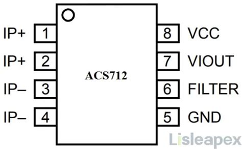
Interfacing the ACS712 Current Sensor
To use the ACS712 current sensor in your project, you need to follow these steps:
- Connect the VCC and GND pins of the sensor to the appropriate power supply (5V).
- Connect the OUT pin of the sensor to an analog input pin of your microcontroller or ADC.
- Connect the current-carrying conductor through the sensor’s aperture, ensuring proper insulation and safety precautions.
- Read the analog voltage output from the sensor using the microcontroller’s ADC.
- Convert the voltage reading to the corresponding current value using the sensitivity factor provided in the datasheet.
Here’s an example code snippet for interfacing the ACS712 current sensor with an Arduino:
const int sensorPin = A0;  // Analog input pin connected to ACS712 output
const float sensitivity = 0.185;  // Sensitivity for ACS712 5A version (185 mV/A)
const float VCC = 5.0;  // Voltage supplied to the sensor
const float QOV = VCC / 2;  // Quiescent Output Voltage (VCC/2)

void setup() {
  Serial.begin(9600);
}

void loop() {
  int sensorValue = analogRead(sensorPin);
  float voltage = sensorValue * (VCC / 1023.0);
  float current = (voltage - QOV) / sensitivity;

  Serial.print("Current: ");
  Serial.print(current);
  Serial.println(" A");

  delay(1000);
}
This code reads the analog voltage from the ACS712 sensor, converts it to the corresponding current value using the sensitivity factor, and prints the current value to the serial monitor.

Applications of the ACS712 Current Sensor
The ACS712 current sensor finds applications in various fields, including:
- Power monitoring systems
- Motor control and protection
- Overcurrent detection and protection
- Battery management systems
- Electrical appliance monitoring
- Renewable energy systems (e.g., solar panel monitoring)
- Automotive systems (e.g., battery current monitoring)
Frequently Asked Questions (FAQ)
1. What is the maximum current that the ACS712 sensor can measure?
The ACS712 sensor is available in three different current ranges: ±5A, ±20A, and ±30A. Choose the appropriate version based on your current measurement requirements.
2. Can the ACS712 sensor measure both AC and DC currents?
Yes, the ACS712 sensor is capable of measuring both AC and DC currents. It provides a linear output voltage proportional to the measured current, regardless of the current direction.
3. How do I calibrate the ACS712 sensor?
To calibrate the ACS712 sensor, you need to measure the output voltage at zero current and at a known current value. Use these measurements to calculate the offset voltage and the sensitivity factor. Adjust your code accordingly to account for any deviations from the ideal values.
4. Can I use the ACS712 sensor with a 3.3V microcontroller?
Yes, you can use the ACS712 sensor with a 3.3V microcontroller. However, you need to ensure that the sensor’s VCC pin is supplied with 5V, as specified in the datasheet. Use a voltage level shifter or a voltage divider to interface the sensor’s output with the 3.3V microcontroller.
5. How do I protect the ACS712 sensor from overcurrent conditions?
The ACS712 sensor has built-in overcurrent protection, but it is recommended to use external protection measures for added safety. Use fuses or circuit breakers in series with the current-carrying conductor to protect against overcurrent conditions that exceed the sensor’s maximum rated current.
Conclusion
The ACS712 current sensor provides a convenient and reliable solution for measuring AC or DC currents in various applications. Its Hall Effect-based sensing principle, electrical isolation, and linear output make it a popular choice among engineers and hobbyists alike.
By understanding the working principle, specifications, and interfacing techniques of the ACS712 sensor, you can effectively integrate it into your projects and accurately measure currents. Remember to follow proper safety guidelines and consider external protection measures when working with high currents.
With the knowledge gained from this comprehensive guide, you are now equipped to utilize the ACS712 current sensor in your electrical and electronic projects, opening up a wide range of possibilities for current monitoring and control.
No responses yet