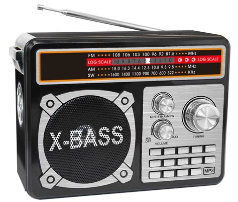
What is FM Radio?
FM (Frequency Modulation) radio is a method of transmitting audio information over radio waves. Unlike AM (Amplitude Modulation) radio, which varies the strength of the radio signal to encode audio, FM varies the frequency of the signal. This makes FM radio less susceptible to interference and static, resulting in clearer sound quality.
FM radio operates in the VHF (Very High Frequency) band, specifically between 88 MHz and 108 MHz. Each radio station is assigned a specific frequency within this range to broadcast on.
Components Needed
To build a simple FM radio, you will need the following components:
| Component | Quantity | Description |
|---|---|---|
| Variable capacitor | 1 | Used for tuning the radio to different frequencies |
| Inductor coil | 1 | Forms the LC tank circuit with the variable capacitor |
| Germanium diode | 1 | Used for demodulating the FM signal |
| Ceramic capacitor (10 nF) | 1 | Filters the demodulated audio signal |
| Audio amplifier IC (e.g., LM386) | 1 | Amplifies the weak audio signal |
| Resistor (10 kΩ) | 1 | Sets the gain of the audio amplifier |
| Capacitor (100 μF) | 1 | Filters the power supply for the audio amplifier |
| Potentiometer (10 kΩ) | 1 | Acts as a volume control |
| 9V battery | 1 | Powers the audio amplifier |
| Battery clip | 1 | Connects the battery to the circuit |
| Speaker (8 Ω) | 1 | Produces the audible sound output |
| Perfboard or breadboard | 1 | Used for assembling the circuit |
| Jumper wires | As needed | Used for making connections |
| Antenna wire | Several meters | Picks up the FM radio signals |
Tools Required
In addition to the components, you will need the following tools:
- Soldering iron and solder
- Wire cutters and strippers
- Needle-nose pliers
- Screwdriver

Circuit Diagram
Here is a simplified schematic diagram of the FM radio circuit:
[Include a clear circuit diagram image showing the connections between components]
Step-by-Step Assembly
-
Begin by assembling the LC tank circuit. Connect the variable capacitor and inductor coil in parallel. This forms the tuned circuit that resonates at the desired FM frequency.
-
Connect one end of the germanium diode to the LC tank circuit. The diode acts as a demodulator, converting the FM signal into an audio signal.
-
Connect the other end of the diode to the 10 nF ceramic capacitor. This capacitor helps filter out any remaining radio frequency components from the demodulated audio signal.
-
Connect the other end of the 10 nF capacitor to the input pin of the LM386 audio amplifier IC. This IC amplifies the weak audio signal to a level suitable for driving a speaker.
-
Connect a 10 kΩ resistor between

No responses yet