What are Circuit Board Headers?
Circuit board headers, also known as pin headers or simply headers, are electrical connectors that consist of a single block of insulating material with multiple metal pins protruding from one or both sides. These pins are designed to be soldered onto a PCB, allowing other components or devices to be connected to the board via mating connectors such as jumper wires, ribbon cables, or female headers.
Headers provide a non-permanent, pluggable connection solution that enables easy assembly, disassembly, and reconfiguration of electronic systems. They are widely used in prototyping, development boards, and various electronic applications where modularity and flexibility are essential.
Types of Circuit Board Headers
There are several types of circuit board headers available, each with its own characteristics and applications. Let’s explore some of the most common types:
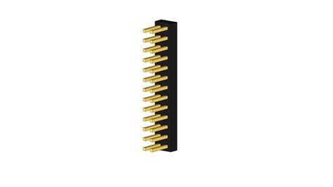
1. Male Headers
Male headers, also known as pin headers, are the most basic type of circuit board headers. They consist of a row of male pins protruding from a single plastic block. The pins are typically arranged in a single row or multiple rows with a specific pitch (distance between the pins).
Male headers are commonly used for:
– Connecting jumper wires or female headers
– Providing access to GPIO pins on development boards
– Establishing connections between PCBs or modules
2. Female Headers
Female headers, also called socket headers, are the counterpart to male headers. They feature a row of female sockets embedded in a plastic block, designed to accept the pins of a male header. Female headers provide a receptacle for plugging in male headers, jumper wires, or other compatible connectors.
Female headers are often used for:
– Providing a socket for plugging in male headers or jumper wires
– Creating stackable shield connections for development boards like Arduino
– Establishing removable connections between PCBs or modules
3. Stackable Headers
Stackable headers are a variation of male headers that allow multiple PCBs or shields to be stacked vertically. They have extra-long pins that protrude from both sides of the plastic block, enabling other PCBs with female headers to be plugged in from above or below.
Stackable headers are commonly used in:
– Arduino shields and compatible development boards
– Modular electronic systems where vertical stacking is required
– Protoboard projects that need extra clearance for components
4. Right-Angle Headers
Right-angle headers, also known as 90-degree headers, have pins that are bent at a 90-degree angle, allowing connections to be made perpendicular to the PCB surface. They are useful when space is limited or when connections need to be made along the edge of a board.
Right-angle headers find applications in:
– Compact electronic devices with limited vertical space
– Establishing connections along the edge of a PCB
– Protoboard projects where side-entry connections are preferred
5. Shrouded Headers
Shrouded headers, also called box headers, have a plastic shroud surrounding the pins, providing a keyed and polarized connection. The shroud prevents incorrect insertion and helps guide the mating connector into place.
Shrouded headers are commonly used for:
– Ensuring proper orientation and preventing accidental misalignment
– Providing a more secure and reliable connection
– Applications where mechanical stability is important

Pin Count and Pitch
When selecting a circuit board header, two important factors to consider are the pin count and pitch.
Pin Count
The pin count refers to the number of pins or positions in a header. Headers are available in various pin counts, ranging from a single pin to 40 pins or more. The choice of pin count depends on the number of signals or connections required for your application.
Common pin counts for headers include:
– 1×2, 1×3, 1×4, 1×5, 1×6, 1×8, 1×10 (single row)
– 2×2, 2×3, 2×4, 2×5, 2×6, 2×8, 2×10 (double row)
Pitch
The pitch is the distance between the centers of adjacent pins in a header. It is a critical parameter that determines compatibility with mating connectors and the overall size of the header.
Common pitch sizes for headers are:
– 2.54 mm (0.1 inches): This is the most standard pitch size, widely used in through-hole components and breadboards.
– 2.00 mm: A smaller pitch size often used in more compact designs or high-density applications.
– 1.27 mm: An even smaller pitch size used in miniaturized electronics or high-density connectors.
The following table summarizes the common pin counts and pitch sizes for circuit board headers:
| Pin Count | Pitch (mm) |
|---|---|
| 1×2 to 1×40 | 2.54 |
| 2×2 to 2×40 | 2.54 |
| 1×2 to 1×40 | 2.00 |
| 2×2 to 2×40 | 2.00 |
| 1×2 to 1×40 | 1.27 |
| 2×2 to 2×40 | 1.27 |

Applications of Circuit Board Headers
Circuit board headers find applications in a wide range of electronic projects and industries. Some common applications include:
1. Prototyping and Development
Headers are extensively used in prototyping and development environments, such as breadboards, protoboards, and development kits. They provide a convenient way to make temporary connections, test circuits, and experiment with different configurations.
2. Modular Electronics
Headers enable modular design approaches in electronics. By using headers, different modules or shields can be easily connected or disconnected from a main board, allowing for flexibility, customization, and expandability. This is particularly useful in systems like Arduino, where shields can be stacked on top of the main board to add functionality.
3. Embedded Systems
In embedded systems, headers are used to establish connections between different PCBs, modules, or peripherals. They provide a reliable and compact way to interface sensors, actuators, displays, and other components with microcontrollers or processing units.
4. Cable Assemblies
Headers are often used in cable assemblies to create custom interconnects between devices or subsystems. They can be crimped or soldered to wires or flat ribbon cables, enabling organized and detachable connections.
5. Test and Measurement
In test and measurement applications, headers provide access points for connecting probes, analyzers, or programming interfaces to the device under test (DUT). They allow easy access to signals, power supplies, or communication buses for debugging, programming, or monitoring purposes.

Considerations When Choosing Circuit Board Headers
When selecting circuit board headers for your project, consider the following factors:
-
Pin Count: Determine the number of pins required based on the number of signals or connections needed in your application.
-
Pitch: Choose a pitch size that is compatible with your PCB layout and mating connectors. Consider the available space and the density of connections required.
-
Orientation: Decide whether you need vertical or right-angle headers based on the mechanical constraints and the desired connection orientation.
-
Mating Connectors: Ensure that the selected header is compatible with the mating connectors you intend to use, such as jumper wires, ribbon cables, or female headers.
-
Current Rating: Consider the maximum current that will flow through the header pins. Choose headers with appropriate current ratings to ensure reliable and safe operation.
-
Solderability: If you plan to solder the headers manually, consider the ease of soldering and the availability of soldering tools and techniques suitable for the header’s pitch and size.
-
Mechanical Stability: For applications that require a sturdy and secure connection, consider using headers with additional mechanical features like latches, locks, or polarizing keys.
-
Environment: Take into account the operating environment of your application, such as temperature range, humidity, vibration, and chemical exposure. Select headers with suitable materials and ratings for your specific environmental conditions.
FAQ
1. What is the difference between male and female headers?
Male headers have pins that protrude from the plastic block, while female headers have sockets that accept the pins of male headers. Male headers are typically used to establish connections, while female headers provide a receptacle for plugging in male headers or other compatible connectors.
2. Can I mix and match headers with different pitches?
Mixing headers with different pitches is not recommended, as it can lead to incompatibility and connection issues. It is important to choose headers and mating connectors with the same pitch to ensure proper fit and reliable connections.
3. How do I determine the current rating of a header?
The current rating of a header depends on factors such as the pin size, material, and ambient temperature. Refer to the manufacturer’s datasheet or specifications to find the maximum current rating for a specific header. It is important to select headers with current ratings that exceed the maximum expected current in your application to avoid overheating or damage.
4. Can I solder headers directly to a PCB?
Yes, headers are designed to be soldered directly onto a PCB. The pins of the header are inserted through the corresponding holes on the PCB and soldered in place. Ensure that the header is properly aligned and seated before soldering, and use appropriate soldering techniques based on the pitch and size of the header.
5. How do I choose the right header for my project?
When selecting a header for your project, consider factors such as the required pin count, pitch, orientation, mating connectors, current rating, solderability, mechanical stability, and environmental conditions. Evaluate your specific requirements and constraints, and choose a header that meets those needs while ensuring compatibility with other components in your system.
Conclusion
Circuit board headers are versatile and essential components in electronics that provide a simple and reliable way to establish electrical connections between PCBs and other devices. Understanding the different types of headers, their pin counts, pitch sizes, and applications is crucial for selecting the right header for your project.
When choosing a header, consider factors such as pin count, pitch, orientation, mating connectors, current rating, solderability, mechanical stability, and environmental conditions. By carefully evaluating your requirements and selecting the appropriate header, you can ensure reliable and efficient connections in your electronic projects.
Whether you are prototyping, designing modular systems, or working on embedded applications, circuit board headers offer a flexible and convenient solution for establishing electrical connections. By leveraging the various types and configurations of headers available, you can create robust and adaptable electronic systems that meet your specific needs.
No responses yet