Introduction to Adders in Digital Electronics
In digital electronics, adders are fundamental building blocks that perform the arithmetic operation of addition. They are essential components in various digital circuits, such as arithmetic logic units (ALUs), processors, and calculators. Adders are designed to add binary numbers and produce a sum and a carry output. The two primary types of adders are the half adder and the full adder.
What is a Half Adder?
A half adder is a digital circuit that performs the addition of two single-bit binary numbers (A and B) and produces a sum (S) and a carry (C) output. The half adder is the simplest form of an adder and is used as a building block for more complex adder circuits.
Half Adder Truth Table
| A | B | S | C |
|---|---|---|---|
| 0 | 0 | 0 | 0 |
| 0 | 1 | 1 | 0 |
| 1 | 0 | 1 | 0 |
| 1 | 1 | 0 | 1 |
The truth table above shows the output of a half adder for all possible combinations of inputs A and B. The sum (S) is the XOR of A and B, while the carry (C) is the AND of A and B.
Half Adder Logic Circuit
The half adder can be implemented using an XOR gate for the sum and an AND gate for the carry. The logic circuit diagram for a half adder is shown below:
    A -----|XOR|---- S
           |   |
    B -----|   |
           |AND|---- C
What is a Full Adder?
A full adder is a digital circuit that performs the addition of three single-bit binary numbers: two operands (A and B) and a carry-in (Cin) from a previous addition. The full adder produces a sum (S) and a carry-out (Cout) as outputs.
Full Adder Truth Table
| A | B | Cin | S | Cout |
|---|---|---|---|---|
| 0 | 0 | 0 | 0 | 0 |
| 0 | 0 | 1 | 1 | 0 |
| 0 | 1 | 0 | 1 | 0 |
| 0 | 1 | 1 | 0 | 1 |
| 1 | 0 | 0 | 1 | 0 |
| 1 | 0 | 1 | 0 | 1 |
| 1 | 1 | 0 | 0 | 1 |
| 1 | 1 | 1 | 1 | 1 |
The truth table above shows the output of a full adder for all possible combinations of inputs A, B, and Cin. The sum (S) is the XOR of A, B, and Cin, while the carry-out (Cout) is the majority function of A, B, and Cin.
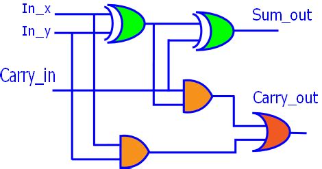
Full Adder Logic Circuit
A full adder can be implemented using two half adders and an OR gate. The logic circuit diagram for a full adder is shown below:
         A ---|XOR|---|XOR|---- S
              |   |   |   |
         B ---|   |   |   |
                  |   |   |
        Cin ------|AND|   |
                      |   |
                      |OR |---- Cout
                      |   |
                  |AND|   |
                  |   |   |
         A -------|   |   |
                      |   |
         B -----------|   |
Key Differences between Half Adder and Full Adder
Number of Inputs
- Half Adder: A half adder has two single-bit binary inputs (A and B).
- Full Adder: A full adder has three single-bit binary inputs: two operands (A and B) and a carry-in (Cin) from a previous addition.
Number of Outputs
- Half Adder: A half adder produces two outputs: a sum (S) and a carry (C).
- Full Adder: A full adder produces two outputs: a sum (S) and a carry-out (Cout).
Complexity
- Half Adder: A half adder is simpler in design and requires fewer logic gates (one XOR gate and one AND gate).
- Full Adder: A full adder is more complex and requires more logic gates (two half adders and an OR gate) to accommodate the additional carry-in input.
Cascading Capability
- Half Adder: Half adders cannot be directly cascaded to create multi-bit adders because they do not have a carry-in input.
- Full Adder: Full adders can be cascaded to create multi-bit adders by connecting the carry-out of one full adder to the carry-in of the next full adder.

Applications of Half Adders and Full Adders
Multi-bit Adders
Full adders are the building blocks for multi-bit adders, such as ripple carry adders and carry lookahead adders. By cascading multiple full adders, it is possible to create adders that can handle larger binary numbers.
Ripple Carry Adder
A ripple carry adder is a multi-bit adder that consists of a series of full adders connected in a chain. The carry-out of each full adder is connected to the carry-in of the next full adder. The drawback of ripple carry adders is that the carry propagation delay increases with the number of bits, making them slower for larger bit widths.
Carry Lookahead Adder
A carry lookahead adder is an optimized multi-bit adder that reduces the carry propagation delay by calculating the carry-in for each stage in advance. This is achieved by using additional logic gates to generate the carry-in signals based on the operands and previous carry-in values. Carry lookahead adders are faster than ripple carry adders but require more hardware.
Arithmetic Logic Units (ALUs)
Half adders and full adders are used in the design of arithmetic logic units (ALUs), which are digital circuits that perform arithmetic and logical operations. ALUs are a critical component in processors and other digital systems that require computation.
Digital Signal Processing
Adders are used in digital signal processing applications, such as digital filters and Fourier transforms. These applications often require high-speed arithmetic operations, and optimized adder circuits are essential for efficient implementation.
Cryptography
Adders are used in various cryptographic algorithms, such as the Advanced Encryption Standard (AES) and the Secure Hash Algorithm (SHA). These algorithms rely on efficient arithmetic operations, including addition, for their security and performance.

Frequently Asked Questions (FAQ)
-
Q: What is the main difference between a half adder and a full adder?
A: The main difference between a half adder and a full adder is that a half adder adds two single-bit binary numbers, while a full adder adds three single-bit binary numbers (two operands and a carry-in from a previous addition). -
Q: Can a half adder be used to create multi-bit adders?
A: No, half adders cannot be directly cascaded to create multi-bit adders because they do not have a carry-in input. To create multi-bit adders, full adders are required. -
Q: What is the advantage of a carry lookahead adder over a ripple carry adder?
A: The advantage of a carry lookahead adder over a ripple carry adder is that it reduces the carry propagation delay by calculating the carry-in for each stage in advance. This makes carry lookahead adders faster than ripple carry adders, especially for larger bit widths. -
Q: In which digital systems are adders commonly used?
A: Adders are commonly used in various digital systems, such as arithmetic logic units (ALUs), processors, digital signal processing applications, and cryptographic algorithms. -
Q: How can the performance of adders be improved for larger bit widths?
A: The performance of adders for larger bit widths can be improved by using optimized adder designs, such as carry lookahead adders, which reduce the carry propagation delay. Additionally, pipelining and parallel processing techniques can be employed to further enhance the speed of arithmetic operations in digital systems.

Conclusion
In conclusion, half adders and full adders are essential building blocks in digital electronics, performing the fundamental arithmetic operation of addition. While half adders are simpler and add two single-bit binary numbers, full adders are more complex and can add three single-bit binary numbers, including a carry-in from a previous addition.
Full adders are the key components in creating multi-bit adders, such as ripple carry adders and carry lookahead adders, which are used in various digital systems, including arithmetic logic units, processors, digital signal processing applications, and cryptographic algorithms.
Understanding the differences between half adders and full adders, as well as their applications, is crucial for designing efficient and optimized digital circuits. As technology advances, the development of faster and more efficient adder designs will continue to play a significant role in the performance of digital systems.
No responses yet