Introduction to Load Cells and the HX711 Amplifier
Load cells are sensors that convert force or weight into an electrical signal. They are widely used for weighing objects in various applications such as industrial scales, kitchen scales, postal scales, etc. Load cells contain a metal body with strain gauges that deform slightly when a load is applied. This deformation causes a change in the electrical resistance of the strain gauges, which can be measured and converted into a weight measurement.
However, the output signal from a load cell is very small, typically in the range of a few millivolts. This makes it difficult to interface directly with a microcontroller or other digital system. That’s where the HX711 comes in. The HX711 is a precision 24-bit analog-to-digital converter (ADC) designed for weighing scales and industrial control applications. It can amplify and digitize the small output signal from a load cell, making it easy to read the weight data with a microcontroller.
In this comprehensive guide, we’ll cover everything you need to know about using load cells with the HX711 amplifier, including:
- Types of load cells and how they work
- Interfacing load cells with the HX711
- Calibrating a load cell scale
- Sample code for reading weight data with an Arduino
- Troubleshooting tips
- Frequently asked questions
By the end of this guide, you’ll have a solid understanding of how to use load cells with the HX711 to build your own digital scale projects. Let’s get started!
Understanding Load Cell Types and Specifications
There are several different types of load cells, each with their own unique characteristics and applications. The most common types are:
1. Strain Gauge Load Cells
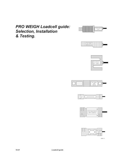
Strain gauge load cells are the most popular type for small to medium scale weighing applications. They consist of a metal body (usually aluminum or stainless steel) with 1-4 strain gauges bonded to it. When a load is applied, the metal body deforms slightly, causing a change in resistance of the strain gauges that can be measured. Strain gauge load cells come in various form factors, such as:
- Beam load cells
- S-type load cells
- Button or disk load cells
- Pancake load cells
2. Hydraulic Load Cells
Hydraulic load cells use a piston and cylinder arrangement filled with hydraulic fluid to measure weight. When a load is applied to the piston, it compresses the fluid and increases the pressure, which can be measured and converted to a weight value. Hydraulic load cells are typically used for very high capacity applications, such as weighing trucks or industrial equipment.
3. Pneumatic Load Cells
Pneumatic load cells are similar to hydraulic ones, but use compressed air instead of fluid. They are less common but offer some advantages such as immunity to temperature changes and the ability to handle hazardous materials.
When selecting a load cell for your application, there are several key specifications to consider:
-
Capacity: The maximum load the cell is rated for, usually specified in kg or lbs. It’s important to choose a load cell with a capacity somewhat higher than your expected maximum weight.
-
Rated Output (RO): The full scale output of the load cell at its rated capacity, typically in millivolts per volt (mV/V). Common values are 1mV/V, 2mV/V, and 3mV/V.
-
Excitation Voltage: The input voltage required to power the load cell, typically 5-10VDC. The HX711 provides 5V excitation.
-
Material: The metal used for the load cell body. Aluminum is common for low cost applications, while stainless steel offers better durability and resistance to corrosion.
-
IP Rating: The degree of protection against dust and moisture. Higher IP ratings are important for harsh environments.
-
Accuracy: The maximum error of the load cell, expressed as a percentage of the rated capacity. Typical values are 0.05%, 0.02%, and 0.01%.
Here is a table summarizing some common load cell specifications:
| Capacity | Rated Output | Excitation Voltage | Material | IP Rating | Accuracy | Typical Application |
|---|---|---|---|---|---|---|
| 1kg | 1mV/V | 5VDC | Aluminum | IP54 | 0.05% | Kitchen scales |
| 10kg | 2mV/V | 5-10VDC | Steel | IP65 | 0.02% | Postal scales |
| 100kg | 3mV/V | 5-12VDC | Steel | IP67 | 0.01% | Platform scales |
| 10,000kg | 2mV/V | 10-15VDC | Stainless | IP68 | 0.05% | Truck scales |

Interfacing Load Cells with the HX711
Now that we’ve covered the basics of load cells, let’s see how to interface them with the HX711 amplifier. The HX711 is a specialized ADC designed specifically for weighing applications. It has two analog input channels (Channel A and Channel B) that can be used to interface with one or two load cells.
The HX711 uses a two-wire interface (Clock and Data) for communication with a microcontroller. It can be powered with 2.6 to 5.5VDC, and provides 5V excitation voltage for the load cell. The HX711 has an internal gain amplifier that can be set to 128 or 64, allowing it to read load cells with different rated outputs.
Here are the basic steps to interface a load cell with the HX711:
-
Connect the load cell’s excitation pins (E+ and E-) to the HX711’s AVDD and AGND pins, respectively.
-
Connect the load cell’s output pins (S+ and S-) to the HX711’s analog input channel (INNA+ and INNA- for Channel A, or INNB+ and INNB- for Channel B).
-
Connect the HX711’s VDD pin to the microcontroller’s 5V pin, and the HX711’s GND pin to the microcontroller’s ground.
-
Connect the HX711’s SCK and DT pins to the microcontroller’s digital I/O pins. These will be used for communication.
-
Power up the system and perform the necessary calibration steps (see next section).
Here is a wiring diagram showing a typical connection between a load cell, HX711, and Arduino microcontroller:
[insert wiring diagram image]
It’s important to use stable, low-noise power supplies for both the HX711 and the microcontroller to minimize fluctuations in the weight readings. Adding decoupling capacitors close to the HX711’s power pins is also recommended.

Calibrating a Load Cell with the HX711
Calibration is an essential step when using load cells, as it establishes the relationship between the HX711’s raw ADC value and the actual weight on the load cell. There are two main parameters that need to be determined during calibration:
-
Zero offset: The ADC value corresponding to zero weight on the load cell. This can drift over time due to temperature changes and other factors, so it’s a good idea to re-calibrate the zero offset periodically.
-
Calibration factor: The scaling factor that converts the ADC value to a weight in the desired units (e.g. grams, pounds, etc.)
Here are the steps to calibrate a load cell with the HX711:
-
Start with no weight on the load cell. Record the raw ADC value from the HX711. This is the zero offset.
-
Place a known weight on the load cell. Record the new raw ADC value.
-
Calculate the difference between the two ADC values. This represents the raw value for the known weight.
-
Divide the known weight by the raw value difference to get the calibration factor. For example, if a 100g weight results in a raw value difference of 20000, the calibration factor would be 100 / 20000 = 0.005 g/unit.
Once you have the zero offset and calibration factor, you can convert any raw ADC reading to a weight value using the formula:
weight = (raw_value - zero_offset) * calibration_factor
It’s a good idea to take multiple calibration readings with different known weights to ensure accuracy across the full range of the load cell. You can then take the average calibration factor.
Here is an example calibration table:
| Known Weight | Raw ADC Value | Zero-Subtracted Value | Calibration Factor |
|---|---|---|---|
| 0g | 100000 | 0 | – |
| 100g | 120000 | 20000 | 0.005 g/unit |
| 500g | 200000 | 100000 | 0.005 g/unit |
| 1000g | 300000 | 200000 | 0.005 g/unit |
| Average | – | – | 0.005 g/unit |
In this example, the zero offset is 100000 and the average calibration factor is 0.005 g/unit. So if we later take a raw reading of 150000, we can calculate the weight as:
weight = (150000 - 100000) * 0.005 = 250g

Sample Arduino Code for Reading Weight Data
Now that we know how to calibrate the load cell, let’s see an example Arduino sketch that reads weight data from the HX711 and prints it to the serial monitor. This code assumes that you have already determined the zero offset and calibration factor values for your setup.
#include "HX711.h"  // import the HX711 library

#define DOUT  3     // HX711 data pin
#define CLK  2      // HX711 clock pin

HX711 scale;        // create a scale object

float calibration_factor = 0.005;  // change this value to the calibration factor you determined
long zero_offset = 100000;         // change this value to your zero offset

void setup() {
  Serial.begin(9600);
  scale.begin(DOUT, CLK);
  scale.set_scale(calibration_factor);
  scale.set_offset(zero_offset);
}

void loop() {
  Serial.print("Weight: ");
  Serial.print(scale.get_units(), 1);  // print weight to 1 decimal place
  Serial.println(" g");
  delay(500);
}
This sketch does the following:
-
Includes the HX711 library and defines the pins used for the data and clock signals.
-
Creates an HX711 object called
scale. -
Defines the calibration factor and zero offset values.
-
In the
setup()function, initializes the serial communication and thescaleobject with the pin numbers, calibration factor, and zero offset. -
In the
loop()function, reads the current weight value usingscale.get_units()and prints it to the serial monitor, along with the units (grams). The weight is printed with 1 decimal place of precision. -
Waits 500ms and repeats the process.
With this sketch loaded on your Arduino and the load cell connected to the HX711 as shown in the wiring diagram, you should see the current weight readings printed to the serial monitor every half second. You can open the serial monitor in the Arduino IDE by clicking on the magnifying glass icon in the upper right corner.
Troubleshooting Tips
If you’re having trouble getting accurate weight readings from your load cell and HX711 setup, here are some troubleshooting tips to try:
-
Check all wiring connections to make sure they are secure and correct. Loose or misplaced wires are a common source of problems.
-
Make sure you are using a stable, low-noise power supply for both the HX711 and the microcontroller. Noisy power can cause fluctuations in the weight readings.
-
Verify that you are using the correct calibration factor and zero offset values for your setup. If these are incorrect, the weight readings will be off.
-
If you are getting negative or wildly fluctuating readings, try re-calibrating the zero offset by removing all weight from the load cell and resetting the offset value in code.
-
If the readings are consistently off by a fixed amount, double-check your calibration factor calculation and make sure you are using a known-good calibration weight.
-
Make sure the load cell is mounted securely and is not being subjected to any off-axis loads or vibrations. These can cause errors in the weight readings.
-
If you are using long wires to connect the load cell to the HX711, make sure they are not picking up any electrical noise. You can try using shielded wires or twisting the wires together to reduce noise pickup.
-
If you are still having trouble, try connecting the load cell to a different HX711 module or a different microcontroller to isolate the problem.
-
Finally, make sure you are using a load cell with specifications that match your application requirements. Using a load cell with the wrong capacity, rated output, or excitation voltage can cause problems.
Frequently Asked Questions
1. What is the difference between Channel A and Channel B on the HX711?
The HX711 has two analog input channels, labeled A and B, that can be used to interface with one or two load cells. Channel A is typically used for a single load cell, while Channel B can be used for a second load cell in applications that require summing the outputs of two cells. The gain of each channel can be set independently to 128 or 64, allowing for flexibility in accommodating different load cell types.
2. Can I use the HX711 with a 3.3V microcontroller?
Yes, the HX711 can be powered with 2.6 to 5.5VDC, so it is compatible with both 5V and 3.3V microcontrollers. However, keep in mind that the HX711’s I/O pins are not 5V tolerant, so if you are using a 5V microcontroller, you will need to use level shifters or voltage dividers to step down the I/O signals to 3.3V.
3. What is the maximum resolution of the HX711?
The HX711 has a 24-bit ADC, which provides a maximum resolution of 16,777,216 counts. However, the actual resolution will depend on the gain setting and the noise level in your system. With a gain of 128 and a 5V excitation voltage, the theoretical resolution is 0.298 microvolts per count. In practice, you can expect to achieve a resolution of a few milligrams with a properly calibrated setup.
4. How often do I need to calibrate my load cell?
The frequency of calibration depends on several factors, such as the stability of your load cell, the environmental conditions, and the accuracy requirements of your application. In general, it’s a good idea to re-calibrate the zero offset periodically (e.g. every few days or weeks) to account for drift due to temperature changes and other factors. The calibration factor should remain stable over time, but you may want to re-check it occasionally (e.g. every few months) to ensure accuracy.
5. Can I use multiple load cells with a single HX711?
Yes, you can use multiple load cells with a single HX711 by connecting them in parallel or by using a summing junction board. When connecting load cells in parallel, make sure they have the same rated output and excitation voltage. The total capacity of the system will be the sum of the individual load cell capacities. Keep in mind that using multiple load cells may increase the overall noise level and reduce the resolution of the system.
Conclusion
In this comprehensive guide, we’ve covered everything you need to know to get started with using load cells and the HX711 amplifier for weighing applications. We’ve discussed the different types of load cells, how to choose the right one for your application, how to interface load cells with the HX711, how to calibrate a load cell scale, and provided sample Arduino code for reading weight data.
By following the steps outlined in this guide and referring to the troubleshooting tips and FAQ section as needed, you should be well on your way to building accurate and reliable weighing systems using load cells and the HX711. Whether you’re building a kitchen scale, a postal scale, or an industrial weighing system, the principles and techniques covered here will serve as a solid foundation for your projects.
As with any engineering project, it’s important to take the time to carefully plan your system, select appropriate components, and perform thorough testing and calibration to ensure optimal performance. Don’t be afraid to experiment and iterate on your designs until you achieve the desired results.
We hope this guide has been informative and helpful in your journey to mastering load cells and the HX711. Happy weighing!
No responses yet