Introduction to TRIAC Symbols
TRIAC, short for Triode for Alternating Current, is a widely used electronic component in power control applications. It is a three-terminal semiconductor device that can conduct current in both directions when triggered, making it an essential component in AC power control circuits. Understanding TRIAC symbols is crucial for anyone working with electronic circuits, as they provide a visual representation of the device’s functionality and connections.
In this comprehensive guide, we will explore the various TRIAC symbols, their meanings, and how to interpret them correctly. Whether you are a beginner in electronics or an experienced technician, this article will provide you with a solid foundation in understanding TRIAC symbols.
The Basic TRIAC Symbol
The most common TRIAC symbol consists of three terminals: Main Terminal 1 (MT1), Main Terminal 2 (MT2), and the Gate (G). The symbol resembles an arrowhead pointing towards MT2, with the gate terminal extending from the side.
| Symbol | Terminal 1 | Terminal 2 | Gate |
|---|---|---|---|
| MT1 | MT2 | G |
The arrowhead in the symbol indicates the direction of conventional current flow when the device is triggered. Current can flow from MT1 to MT2 or from MT2 to MT1, depending on the polarity of the voltage applied across the main terminals and the triggering of the gate terminal.

Variations in TRIAC Symbols
While the basic TRIAC symbol is the most common representation, there are some variations in symbols used by different manufacturers or in different contexts. These variations may include additional information or slightly different designs, but they all represent the same fundamental device.
TRIAC Symbol with Polarity Indication
Some TRIAC symbols include polarity markings to indicate the device’s behavior when triggered with positive or negative gate voltages. In this case, the symbol may have a ‘+’ sign near the gate terminal to denote positive triggering and a ‘-‘ sign for negative triggering.
| Symbol | Positive Triggering | Negative Triggering |
|---|---|---|
| + | – |
It is important to note that not all TRIAC symbols include polarity markings, and the absence of these markings does not necessarily mean the device is not sensitive to gate polarity.
TRIAC Symbol with Trigger Quadrants
In some cases, TRIAC symbols may include information about the device’s trigger quadrants. A TRIAC can be triggered in four different quadrants, depending on the polarity of the voltage across the main terminals and the gate voltage.
| Quadrant | MT2 Polarity | Gate Polarity |
|---|---|---|
| I | + | + |
| II | + | – |
| III | – | – |
| IV | – | + |
TRIAC symbols with trigger quadrant information usually have the quadrant numbers (I, II, III, IV) marked near the gate terminal.
| Symbol | Quadrant I | Quadrant II | Quadrant III | Quadrant IV |
|---|---|---|---|---|
| I | II | III | IV |
Understanding the trigger quadrants is essential for properly controlling the TRIAC in your circuit design.

Identifying TRIAC Terminals
Correctly identifying the terminals of a TRIAC is crucial for proper circuit connections. The three terminals – MT1, MT2, and Gate – each serve a specific purpose:
-
Main Terminal 1 (MT1): This terminal is one of the two main current-carrying terminals of the TRIAC. It is connected to one side of the load in the circuit.
-
Main Terminal 2 (MT2): MT2 is the other main current-carrying terminal of the TRIAC. It is connected to the other side of the load in the circuit.
-
Gate (G): The gate terminal is used to trigger the TRIAC into conduction. A small current applied to the gate terminal, with respect to MT1, is sufficient to turn on the device.
In the physical device, the terminals are usually arranged in a triangular pattern, with MT1 and MT2 on opposite sides and the gate terminal at the top or bottom.
| Physical Device | Terminal Arrangement |
|---|---|
Always refer to the manufacturer’s datasheet for the specific device you are using to ensure correct terminal identification and connection.

Triggering a TRIAC
To control the flow of current through a TRIAC, it must be properly triggered. Triggering a TRIAC involves applying a small current to the gate terminal with respect to MT1. The gate trigger current (IGT) and voltage (VGT) required to turn on the device vary depending on the specific TRIAC and the operating quadrant.
Gate Trigger Characteristics
The gate trigger characteristics of a TRIAC are typically specified in the manufacturer’s datasheet. These characteristics include:
-
Gate Trigger Current (IGT): The minimum gate current required to turn on the TRIAC in a given quadrant.
-
Gate Trigger Voltage (VGT): The minimum gate voltage required to turn on the TRIAC in a given quadrant.
These values are usually specified for each quadrant and may vary depending on the temperature and the rate of change of the main terminal voltage (dV/dt).
Triggering Circuits
To trigger a TRIAC, a triggering circuit is used to apply the necessary gate current and voltage. The most common triggering circuits include:
-
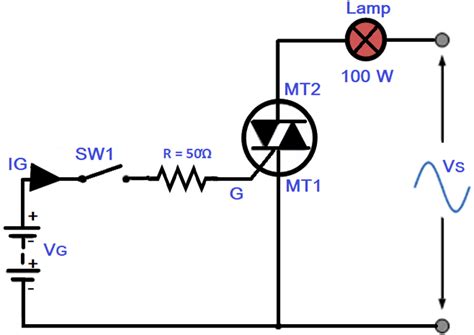
Resistive Triggering: A simple resistor is connected between the gate and MT2 to limit the gate current. This method is suitable for low-power applications.
-
Opto-isolator Triggering: An opto-isolator is used to provide electrical isolation between the control circuit and the TRIAC. This method is useful in applications where noise immunity and safety are important.
-
Diac Triggering: A Diac (Diode for Alternating Current) is used to provide a breakover voltage for triggering the TRIAC. This method is commonly used in phase control applications.
The choice of triggering circuit depends on the specific application requirements, such as power level, noise immunity, and isolation.
TRIAC Applications
TRIACs are widely used in various power control applications due to their ability to control AC power efficiently. Some common applications include:
-
Dimming Circuits: TRIACs are used in light dimming circuits to control the brightness of lamps and LEDs by varying the power delivered to the load.
-
Motor Speed Control: TRIACs can be used to control the speed of AC motors by adjusting the voltage or current supplied to the motor windings.
-
Temperature Control: In temperature control systems, TRIACs are used to regulate the power delivered to heating elements, such as in electric ovens or Soldering Irons.
-
Power Switching: TRIACs can be used as solid-state relays to switch AC loads on and off, replacing mechanical relays in various applications.
-
Voltage Regulation: TRIACs are used in voltage stabilizers and regulators to maintain a constant output voltage by controlling the input voltage.
These are just a few examples of the many applications where TRIACs are used for efficient power control.
Safety Considerations
When working with TRIACs and power control circuits, it is essential to keep safety in mind. Some important safety considerations include:
-
Voltage and Current Ratings: Always ensure that the TRIAC chosen for your application has the appropriate voltage and current ratings to handle the expected load safely.
-
Heat Dissipation: TRIACs generate heat during operation, especially when controlling large loads. Proper heat sinking and thermal management are crucial to prevent device failure and ensure reliable operation.
-
Isolation: In applications where the control circuit and the power circuit must be electrically isolated, use opto-isolators or other isolation techniques to prevent potential hazards.
-
Circuit Protection: Incorporate appropriate protection measures, such as fuses or circuit breakers, to safeguard the TRIAC and the connected circuitry from overcurrent or short-circuit conditions.
-
High Voltage Precautions: When working with high-voltage AC circuits, always follow proper safety guidelines, such as using insulated tools, wearing protective gear, and ensuring that the circuit is properly de-energized before conducting any work.
By understanding and adhering to these safety considerations, you can work with TRIACs and power control circuits effectively and safely.
Frequently Asked Questions (FAQ)
-
Q: What is the difference between a TRIAC and an SCR (Silicon Controlled Rectifier)?
A: While both TRIACs and SCRs are thyristors used for power control, the main difference is that a TRIAC can conduct current in both directions, whereas an SCR can only conduct current in one direction. TRIACs are commonly used for AC power control, while SCRs are used for DC power control or rectification. -
Q: Can a TRIAC be used to control DC loads?
A: No, TRIACs are designed specifically for controlling AC loads. For DC power control, other devices like MOSFETs, BJTs, or SCRs are more suitable. -
Q: What happens if the gate trigger current is too low?
A: If the gate trigger current is below the minimum required value (IGT), the TRIAC will not turn on, and no current will flow through the main terminals. It is essential to provide sufficient gate current to ensure proper triggering of the device. -
Q: How do I select the appropriate TRIAC for my application?
A: When selecting a TRIAC, consider factors such as the maximum voltage and current ratings of the load, the required trigger currents and voltages, the operating temperature range, and the desired package type. Refer to the manufacturer’s datasheets and application notes for guidance on selecting the appropriate device for your specific application. -
Q: Can TRIACs be used in parallel for higher current handling?
A: While it is possible to connect TRIACs in parallel for increased current handling capacity, it is not recommended without proper precautions. Paralleling TRIACs can lead to uneven current sharing and potential device failure due to differences in device characteristics. If parallel operation is necessary, use matched devices and ensure proper gate synchronization and load balancing.
Conclusion
Understanding TRIAC symbols is essential for anyone working with power control circuits. This comprehensive guide has covered the basic TRIAC symbol, its variations, terminal identification, triggering methods, applications, and safety considerations.
By familiarizing yourself with TRIAC symbols and their meanings, you can effectively design, troubleshoot, and work with power control circuits that incorporate these versatile devices. Remember to always refer to the manufacturer’s datasheets for specific device information and to follow proper safety guidelines when working with high-voltage AC circuits.
With this knowledge, you are well-equipped to tackle a wide range of power control applications using TRIACs, from light dimming and motor speed control to temperature regulation and power switching. As you gain more experience working with these devices, you will develop a deeper understanding of their capabilities and limitations, enabling you to create more efficient and robust power control solutions.
No responses yet