Introduction to Flexible PCB
A Flexible PCB, also known as a flex circuit or flexible printed circuit board, is a type of printed circuit board that is designed to be flexible and bendable. Unlike traditional rigid PCBs, flexible PCBs can conform to various shapes and sizes, making them ideal for applications where space is limited or where the circuit needs to be bent or folded.
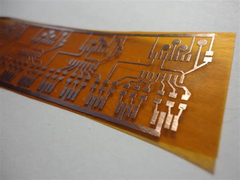
Flexible PCBs are made from a thin, flexible substrate, typically polyimide or polyester, which is coated with a conductive material, such as copper. The circuitry is then etched onto the substrate using a photolithographic process, similar to the process used for rigid PCBs. The resulting circuit is thin, lightweight, and highly flexible, allowing it to be bent, twisted, or folded without damaging the circuitry.
Advantages of Flexible PCBs
Flexible PCBs offer several advantages over traditional rigid PCBs, including:
- Space savings: Flexible PCBs can be bent or folded to fit into tight spaces, reducing the overall size of the device.
- Weight reduction: Flexible PCBs are typically thinner and lighter than rigid PCBs, making them ideal for portable devices or aerospace applications.
- Increased reliability: Flexible PCBs are less prone to cracking or breaking under stress, which can improve the overall reliability of the device.
- Improved thermal management: Flexible PCBs can be designed with thermal management features, such as heat sinks or thermal vias, to help dissipate heat more effectively.
- Enhanced signal integrity: Flexible PCBs can be designed with controlled impedance and shielding features to improve signal integrity and reduce electromagnetic interference (EMI).
Applications of Flexible PCBs
Flexible PCBs are used in a wide range of applications, including:
- Consumer electronics: Flexible PCBs are commonly used in smartphones, tablets, laptops, and wearable devices, where space is limited and flexibility is required.
- Medical devices: Flexible PCBs are used in medical devices, such as hearing aids, pacemakers, and implantable sensors, where reliability and biocompatibility are critical.
- Automotive electronics: Flexible PCBs are used in automotive applications, such as infotainment systems, dashboard displays, and sensors, where vibration and temperature extremes are common.
- Aerospace and defense: Flexible PCBs are used in aerospace and defense applications, such as satellites, unmanned aerial vehicles (UAVs), and military communications equipment, where weight and space are critical factors.
- Industrial automation: Flexible PCBs are used in industrial automation applications, such as robotics, motion control, and machine vision systems, where flexibility and durability are important.
Types of Flexible PCBs
There are several types of flexible PCBs, each with its own unique characteristics and applications. The most common types of flexible PCBs include:
Single-sided Flexible PCBs
Single-sided flexible PCBs have circuitry on only one side of the substrate. They are the simplest and most cost-effective type of flexible PCB, making them ideal for low-cost, low-complexity applications.
Double-sided Flexible PCBs
Double-sided flexible PCBs have circuitry on both sides of the substrate, allowing for higher component density and more complex designs. They are commonly used in applications where space is limited, such as smartphones and wearable devices.
Multi-layer Flexible PCBs
Multi-layer flexible PCBs have three or more conductive layers, separated by insulating layers. They offer the highest component density and design complexity, making them ideal for applications that require high performance and reliability, such as aerospace and defense.
Rigid-Flex PCBs
Rigid-flex PCBs combine both rigid and flexible sections on the same board. The rigid sections provide structural support and allow for the mounting of components, while the flexible sections allow for bending and folding. Rigid-flex PCBs are commonly used in applications where both flexibility and rigidity are required, such as medical devices and automotive electronics.

Flexible PCB Materials
Flexible PCBs are made from a variety of materials, each with its own unique properties and characteristics. The most common materials used in flexible PCBs include:
Polyimide
Polyimide is the most commonly used substrate material for flexible PCBs. It offers excellent thermal stability, chemical resistance, and mechanical strength, making it ideal for high-reliability applications. Polyimide is also biocompatible, making it suitable for medical applications.
Polyester
Polyester is another common substrate material for flexible PCBs. It offers good electrical properties and is less expensive than polyimide, making it ideal for low-cost applications. However, polyester has lower thermal stability and mechanical strength than polyimide.
Copper
Copper is the most commonly used conductive material for flexible PCBs. It offers excellent electrical conductivity and is relatively inexpensive. However, copper is prone to oxidation and can be difficult to solder.
Other Materials
Other materials used in flexible PCBs include:
- Adhesives: Used to bond the layers of the flexible PCB together.
- Coverlay: Used to protect the circuitry from moisture and other environmental factors.
- Stiffeners: Used to provide additional support and rigidity to the flexible PCB.

Flexible PCB Manufacturing Process
The manufacturing process for flexible PCBs is similar to that of rigid PCBs, with a few key differences. The basic steps in the flexible PCB manufacturing process include:
- Design: The circuit is designed using computer-aided design (CAD) software, taking into account the specific requirements of the application.
- Substrate preparation: The substrate material is cut to size and cleaned to remove any contaminants.
- Conductive layer application: The conductive material, typically copper, is applied to the substrate using a process called lamination.
- Photolithography: The circuit pattern is transferred onto the conductive layer using a photolithographic process.
- Etching: The unwanted copper is removed using a chemical etching process, leaving only the desired circuit pattern.
- Coverlay application: A protective coverlay is applied to the circuit to protect it from moisture and other environmental factors.
- Drilling and cutting: Holes are drilled in the circuit board to allow for the mounting of components, and the board is cut to its final shape and size.
- Surface finishing: The exposed copper is coated with a protective finish, such as gold or silver, to prevent oxidation and improve solderability.
- Testing and inspection: The finished flexible PCB is tested and inspected to ensure that it meets the required specifications and performance standards.

Designing Flexible PCBs
Designing flexible PCBs requires a different approach than designing rigid PCBs. Some key considerations when designing flexible PCBs include:
Bend Radius
The bend radius is the minimum radius that the flexible PCB can be bent without damaging the circuitry. The bend radius is determined by the thickness and material of the substrate, as well as the location and orientation of the components.
Component Placement
Component placement is critical in flexible PCB design. Components should be placed in areas of the circuit that will not be subjected to excessive bending or stress. Additionally, components should be oriented in a way that minimizes the stress on the solder joints.
Trace Width and Spacing
Trace width and spacing are important factors in flexible PCB design. Traces should be wide enough to carry the required current without overheating, but not so wide that they become too stiff. Additionally, traces should be spaced far enough apart to prevent short circuits and crosstalk.
Stiffeners
Stiffeners can be used to provide additional support and rigidity to the flexible PCB in areas where components are mounted or where the circuit is subjected to stress. Stiffeners are typically made from materials such as polyimide or FR-4.
Shielding
Shielding can be used to protect the circuitry from electromagnetic interference (EMI) and radio frequency interference (RFI). Shielding can be achieved through the use of conductive materials, such as copper or aluminum, or through the use of shielding tapes or coatings.
Flexible PCB Assembly
Assembling flexible PCBs requires specialized equipment and techniques to ensure that the components are properly mounted and the circuit is not damaged during the assembly process. Some key considerations when assembling flexible PCBs include:
Soldering
Soldering flexible PCBs requires a different approach than soldering rigid PCBs. The solder joints must be able to withstand the repeated bending and flexing of the circuit without cracking or breaking. Additionally, the soldering temperature and time must be carefully controlled to prevent damage to the substrate material.
Adhesives
Adhesives are commonly used in flexible PCB assembly to bond components to the substrate and to provide additional support and strain relief. The choice of adhesive depends on the specific requirements of the application, such as temperature range, chemical resistance, and flexibility.
Connectors
Connectors are critical components in flexible PCB assembly, as they provide a means of connecting the flexible circuit to other components or devices. The choice of connector depends on the specific requirements of the application, such as current carrying capacity, mating cycles, and environmental resistance.
Strain Relief
Strain relief is an important consideration in flexible PCB assembly, as it helps to prevent damage to the circuit and components due to repeated bending and flexing. Strain relief can be achieved through the use of strain relief features, such as curves or loops in the circuit, or through the use of strain relief materials, such as elastomers or thermoplastics.
Flexible PCB Testing and Inspection
Testing and inspection are critical steps in the flexible PCB manufacturing process, as they ensure that the circuit meets the required performance and reliability standards. Some common testing and inspection methods for flexible PCBs include:
Visual Inspection
Visual inspection is used to check for obvious defects, such as cracks, voids, or misaligned components. Visual inspection can be performed using a microscope or other magnification device.
Electrical Testing
Electrical testing is used to verify that the circuit is functioning as intended and that there are no short circuits or open circuits. Electrical testing can be performed using specialized test equipment, such as a multimeter or oscilloscope.
Environmental Testing
Environmental testing is used to ensure that the flexible PCB can withstand the expected environmental conditions, such as temperature, humidity, and vibration. Environmental testing can be performed using specialized test chambers or by subjecting the circuit to real-world conditions.
Mechanical Testing
Mechanical testing is used to verify that the flexible PCB can withstand the expected mechanical stresses, such as bending, twisting, and folding. Mechanical testing can be performed using specialized test equipment, such as a bend tester or a twist tester.
Flexible PCB Standards and Certifications
There are several standards and certifications that apply to flexible PCBs, depending on the specific application and industry. Some common standards and certifications include:
IPC Standards
The IPC (Association Connecting Electronics Industries) is a global trade association that develops standards for the electronics industry. Some key IPC standards that apply to flexible PCBs include:
- IPC-2223: Design Standard for Flexible Printed Boards
- IPC-4101: Specification for Base Materials for Rigid and Multilayer Printed Boards
- IPC-4202: Flexible Base Dielectrics for Use in Flexible Printed Circuitry
- IPC-4203: Adhesive Coated Dielectric Films for Use as Cover Sheets for Flexible Printed Circuitry and Flexible Adhesive Bonding Films
- IPC-4204: Flexible Metal-Clad Dielectrics for Use in Fabrication of Flexible Printed Circuitry
- IPC-6013: Qualification and Performance Specification for Flexible Printed Boards
UL Standards
Underwriters Laboratories (UL) is a global safety certification company that develops standards for safety and performance. Some key UL standards that apply to flexible PCBs include:
- UL 94: Standard for Safety of Flammability of Plastic Materials for Parts in Devices and Appliances
- UL 796: Standard for Safety of Printed-Wiring Boards
RoHS Certification
The Restriction of Hazardous Substances (RoHS) is a directive that restricts the use of certain hazardous substances in electrical and electronic equipment. To be RoHS compliant, flexible PCBs must not contain more than the allowable levels of lead, mercury, cadmium, hexavalent chromium, polybrominated biphenyls (PBB), and polybrominated diphenyl ethers (PBDE).
Flexible PCB Industry and Market Trends
The flexible PCB industry is a rapidly growing and evolving market, driven by increasing demand for smaller, lighter, and more flexible electronic devices. Some key trends and market drivers in the flexible PCB industry include:
Miniaturization
The trend towards miniaturization is driving demand for smaller and more compact electronic devices, which in turn is driving demand for flexible PCBs that can be bent or folded to fit into tight spaces.
Wearable Electronics
The growing popularity of wearable electronic devices, such as smartwatches and fitness trackers, is driving demand for flexible PCBs that can conform to the shape of the human body and withstand the stresses of daily wear and tear.
5G and IoT
The deployment of 5G networks and the growth of the Internet of Things (IoT) is driving demand for flexible PCBs that can be used in a wide range of applications, from automotive electronics to industrial automation.
Sustainable Electronics
The trend towards sustainable electronics is driving demand for flexible PCBs that are made from eco-friendly materials and that can be easily recycled or disposed of at the end of their lifecycle.
According to a report by Grand View Research, the global flexible PCB market size was valued at USD 15.2 billion in 2020 and is expected to grow at a compound annual growth rate (CAGR) of 11.7% from 2021 to 2028. The growth of the flexible PCB market is being driven by increasing demand from the consumer electronics, automotive, and healthcare industries, as well as the growing adoption of 5G technology and the Internet of Things (IoT).
Frequently Asked Questions (FAQ)
-
What is the difference between a flexible PCB and a rigid PCB?
A flexible PCB is designed to be bendable and can conform to various shapes, while a rigid PCB is stiff and cannot be bent or flexed. Flexible PCBs are typically thinner and lighter than rigid PCBs, making them ideal for applications where space is limited or where the circuit needs to be bent or folded. -
What are the advantages of using a flexible PCB?
Some of the main advantages of using a flexible PCB include: - Space savings: Flexible PCBs can be bent or folded to fit into tight spaces, reducing the overall size of the device.
- Weight reduction: Flexible PCBs are typically thinner and lighter than rigid PCBs, making them ideal for portable devices or aerospace applications.
- Increased reliability: Flexible PCBs are less prone to cracking or breaking under stress, which can improve the overall reliability of the device.
- Improved thermal management: Flexible PCBs can be designed with thermal management features, such as heat sinks or thermal vias, to help dissipate heat more effectively.
-
Enhanced signal integrity: Flexible PCBs can be designed with controlled impedance and shielding features to improve signal integrity and reduce electromagnetic interference (EMI).
-
What are some common applications for flexible PCBs?
Flexible PCBs are used in a wide range of applications, including: - Consumer electronics: smartphones, tablets, laptops, and wearable devices
- Medical devices: hearing aids, pacemakers, and implantable sensors
- Automotive electronics: infotainment systems, dashboard displays, and sensors
- Aerospace and defense: satellites, unmanned aerial vehicles (UAVs), and military communications equipment
-
Industrial automation: robotics, motion control, and machine vision systems
-
What materials are commonly used in flexible PCBs?
The most common materials used in flexible PCBs include: - Polyimide: a substrate material that offers excellent thermal stability, chemical resistance, and mechanical strength
- Polyester: a substrate material that offers good electrical properties and is less expensive than polyimide
- Copper: the most commonly used conductive material for flexible PCBs, offering excellent electrical conductivity
- Adhesives: used to bond the layers of the flexible PCB together
- Coverlay: used to protect the circuitry from moisture and other environmental factors
-
Stiffeners: used to provide additional support and rigidity to the flexible PCB
-
What are some key considerations when designing a flexible PCB?
Some key considerations when designing a flexible PCB include: - Bend radius: the minimum radius that the flexible PCB can be bent without damaging the circuitry
- Component placement: components should be placed in areas of the circuit that will not be subjected to excessive bending or stress
- Trace width and spacing: traces should be wide enough to carry the required current without overheating, but not so wide that they become too stiff
- Stiffeners: can be used to provide additional support and rigidity to the flexible PCB in areas where components are mounted or where the circuit is subjected to stress
- Shielding: can be used to protect the circuitry from electromagnetic interference (EMI) and radio frequency interference (RFI)
In conclusion, flexible PCBs offer a unique set of advantages and challenges compared to traditional rigid PCBs. They are ideal for applications where space is limited, weight is a concern, or where
No responses yet