Arduino Nano Specifications
Before diving into the pinout details, let’s review the key specifications of the Arduino Nano:
| Specification | Arduino Nano (3.x) | Arduino Nano (2.x) |
|---|---|---|
| Microcontroller | ATmega328P | ATmega168 |
| Operating Voltage | 5V | 5V |
| Input Voltage (recommended) | 7-12V | 7-12V |
| Input Voltage (limit) | 6-20V | 6-20V |
| Digital I/O Pins | 14 (6 provide PWM output) | 14 (6 provide PWM output) |
| Analog Input Pins | 8 | 8 |
| DC Current per I/O Pin | 40 mA | 40 mA |
| Flash Memory | 32 KB (ATmega328P), 2 KB used by bootloader | 16 KB (ATmega168), 2 KB used by bootloader |
| SRAM | 2 KB (ATmega328P) | 1 KB (ATmega168) |
| EEPROM | 1 KB (ATmega328P) | 512 bytes (ATmega168) |
| Clock Speed | 16 MHz | 16 MHz |
| Dimensions | 18 x 45 mm | 18 x 45 mm |
| Weight | 7 g | 7 g |
The Arduino Nano offers a compact size while providing a good number of digital and analog pins for interfacing with various sensors, actuators, and peripherals.
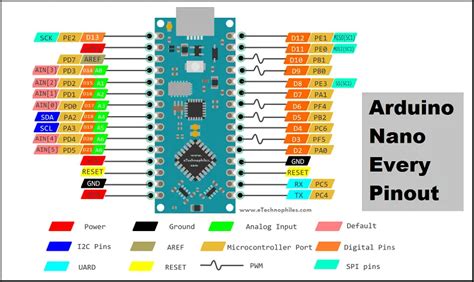
Arduino Nano Pinout Diagram
To understand the Arduino Nano pinout, let’s take a look at the pinout diagram:
                     +-----+
         +------------| USB |------------+
         |            +-----+            |
    B5   | [ ]D13/SCK        MISO/D12[ ] |   B4
         | [ ]3.3V           MOSI/D11[ ]~|   B3
         | [ ]V.ref     ___    SS/D10[ ]~|   B2
    C0   | [ ]A0       / N \       D9[ ]~|   B1
    C1   | [ ]A1      /  A  \      D8[ ] |   B0
    C2   | [ ]A2      \  N  /      D7[ ] |   D7
    C3   | [ ]A3       \_0_/       D6[ ]~|   D6
    C4   | [ ]A4/SDA               D5[ ]~|   D5
    C5   | [ ]A5/SCL               D4[ ] |   D4
         | [ ]A6              INT1/D3[ ]~|   D3
    C6   | [ ]A7              INT0/D2[ ] |   D2
    D0  -| [ ]D0/RX                GND[ ] |
    D1  -| [ ]D1/TX                RST[ ] |   C6
         | [ ]GND                  RX1[ ] |   D0
         | [ ]RST                  TX1[ ] |   D1
         | [ ]5V                   VIN[ ] |
         +-------------------------------+
The Arduino Nano pinout consists of several types of pins:
- Digital I/O Pins (D0-D13): These pins can be used for digital input or output. Some of them have additional functionality, such as PWM, external interrupts, or serial communication.
- Analog Input Pins (A0-A7): These pins can be used to read analog voltage levels from sensors or other devices.
- Power Pins (5V, 3.3V, GND, VIN): These pins provide power to the Arduino Nano and connected devices. The 5V and 3.3V pins supply regulated power, while VIN is used to supply external power to the board.
- Serial Communication Pins (RX, TX): These pins are used for serial communication with other devices or a computer via USB.
- SPI Pins (MOSI, MISO, SCK, SS): These pins are used for SPI (Serial Peripheral Interface) communication with compatible devices.
- I2C Pins (SDA, SCL): These pins are used for I2C (Inter-Integrated Circuit) communication with compatible devices.

Arduino Nano Pin Descriptions
Now, let’s explore the functionality of each pin in more detail:
Digital I/O Pins
- D0 (RX) and D1 (TX): These pins are used for serial communication. D0 is the receive pin (RX), and D1 is the transmit pin (TX). When using serial communication, avoid using these pins for other purposes.
- D2 and D3: These pins can be used as external interrupt pins (INT0 and INT1, respectively) to trigger an interrupt based on a change in the pin state.
- D3, D5, D6, D9, D10, and D11: These pins support PWM (Pulse Width Modulation) output, which allows you to generate analog-like signals by varying the duty cycle of a digital signal.
- D10 (SS), D11 (MOSI), D12 (MISO), and D13 (SCK): These pins are used for SPI communication. SS is the Slave Select pin, MOSI is Master Out Slave In, MISO is Master In Slave Out, and SCK is the Serial Clock.
- D4, D7, D8, and D12: These are general-purpose digital I/O pins that can be used for input or output.
Analog Input Pins
- A0 to A7: These pins can be used to read analog voltage levels from sensors or other devices. The analog inputs have a resolution of 10 bits, providing values ranging from 0 to 1023.
- A4 (SDA) and A5 (SCL): These pins can also be used for I2C communication. SDA is the Serial Data pin, and SCL is the Serial Clock pin.
- A6 and A7: These pins are only available on the Arduino Nano 3.x boards and cannot be used as digital I/O pins.
Power Pins
- 5V: This pin provides regulated 5V power to the Arduino Nano and connected devices. It can be used to power external components or receive power from an external regulated 5V supply.
- 3.3V: This pin provides regulated 3.3V power, which can be used to power devices that require a lower voltage.
- GND: These pins are the ground connections for the Arduino Nano and connected devices.
- VIN: This pin is used to supply external power to the Arduino Nano when not powered via USB. The input voltage range is 6-20V, but the recommended range is 7-12V.
Reset Pin
- RST: This pin is used to reset the Arduino Nano. When connected to ground, it resets the microcontroller.

Programming the Arduino Nano
Programming the Arduino Nano is similar to programming other Arduino boards. You can use the Arduino IDE (Integrated Development Environment) to write, compile, and upload sketches to the board. Here are the basic steps to get started:
- Connect your Arduino Nano to your computer using a USB cable.
- Open the Arduino IDE and select the appropriate board and port from the “Tools” menu.
- Write your sketch or program in the IDE using the Arduino programming language, which is based on C/C++.
- Compile the sketch by clicking the “Verify” button to check for any errors.
- Upload the compiled sketch to the Arduino Nano by clicking the “Upload” button.
- The sketch will start running on the Arduino Nano immediately after the upload is complete.
When programming the Arduino Nano, keep in mind the specific pin functions and capabilities discussed earlier. Use the appropriate pins for digital I/O, analog input, PWM, serial communication, SPI, or I2C based on your project requirements.

Arduino Nano Pinout FAQ
- Q: What is the difference between Arduino Nano 3.x and 2.x?
A: The main differences between Arduino Nano 3.x and 2.x are the microcontroller and memory specifications. Arduino Nano 3.x uses the ATmega328P microcontroller with 32 KB of flash memory, 2 KB of SRAM, and 1 KB of EEPROM. Arduino Nano 2.x, on the other hand, uses the ATmega168 microcontroller with 16 KB of flash memory, 1 KB of SRAM, and 512 bytes of EEPROM.
- Q: Can I use the analog pins as digital I/O pins?
A: Yes, you can use the analog pins (A0-A7) as digital I/O pins. However, keep in mind that A6 and A7 are only available on the Arduino Nano 3.x boards and cannot be used as digital I/O pins.
- Q: How do I power the Arduino Nano?
A: You can power the Arduino Nano using a USB cable connected to your computer or an external power source through the VIN pin. The recommended input voltage range is 7-12V, but the board can handle 6-20V. When using an external power source, make sure to connect the ground (GND) pin as well.
- Q: What is the maximum current that each I/O pin can provide?
A: Each I/O pin on the Arduino Nano can provide a maximum current of 40 mA. However, it is recommended to limit the current to 20 mA per pin to avoid potential damage to the board.
- Q: Can I use the Arduino Nano for I2C or SPI communication?
A: Yes, the Arduino Nano supports both I2C and SPI communication protocols. For I2C, you can use pins A4 (SDA) and A5 (SCL). For SPI, you can use pins D10 (SS), D11 (MOSI), D12 (MISO), and D13 (SCK).
Conclusion
The Arduino Nano is a powerful and compact microcontroller board that offers a wide range of capabilities for your projects. Understanding the Arduino Nano pinout is crucial for effectively utilizing its features and interfacing with various sensors, actuators, and peripherals.
In this article, we covered the specifications of the Arduino Nano, provided a detailed pinout diagram, and explained the functionality of each pin. We also discussed the programming aspects and answered some frequently asked questions about the Arduino Nano pinout.
With this knowledge, you can confidently use the Arduino Nano in your projects, whether you’re building a simple LED blinker or a complex IoT device. Remember to refer to the pinout diagram and pin descriptions when connecting components and writing your sketches.
Happy tinkering with your Arduino Nano!
No responses yet