Introduction to Pulse Width Modulation
Pulse Width Modulation is a method of encoding analog signal levels into digital signals. It works by rapidly switching a power source on and off, creating a pulse train. The width of these pulses (the time the signal is in the “on” state) is modulated to encode a specific analog signal level.
Basic Principles of PWM
The basic principle behind PWM is that the average voltage (and current) fed to the load is controlled by turning the switch between the power source and load on and off at a fast rate. The longer the switch is on compared to the off periods, the higher the total power supplied to the load.
The PWM signal has a repeating period, and the frequency of the PWM signal is the inverse of this period. The duty cycle describes the proportion of “on” time to the regular interval or period of time.
Duty Cycle (%) = (Pulse Width / Period) × 100
For example, a PWM signal with a 50% duty cycle would be on half the time and off half the time. A signal with a 75% duty cycle would be on for 75% of the period and off for 25%.
How PWM Works
A PWM signal consists of two main components: a duty cycle and a frequency. The duty cycle describes the amount of time the signal is in a high (on) state as a percentage of the total time it takes to complete one cycle. The frequency determines how fast the PWM completes a cycle (i.e. 1000 Hz would be 1000 cycles per second).
Generating PWM Signals
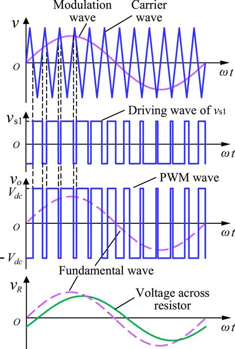
PWM signals are typically generated using a comparator with two inputs: a reference signal and a periodic sawtooth or triangular waveform. When the reference signal is higher than the modulation waveform, the PWM signal is in the high state. When the reference is lower, the PWM signal is in the low state.
By changing the reference signal, the duty cycle of the PWM can be modified. This is how PWM is used to encode analog signal levels.
Filtering PWM Signals
PWM signals can be converted back into analog voltages by passing them through a low-pass filter. The filter eliminates the high-frequency switching and recovers the average voltage of the PWM signal, which corresponds to the original analog signal level.
The cut-off frequency of the low-pass filter needs to be significantly lower than the PWM frequency for effective smoothing.

Applications of PWM
PWM finds applications in a wide variety of systems, including:
Motor Speed Control
PWM is widely used in motor speed control applications. By adjusting the duty cycle of the PWM signal, the average voltage supplied to the motor can be varied, which in turn controls the motor’s speed.
LED Dimming
PWM is an effective method for dimming LEDs. By rapidly switching the LED on and off and varying the duty cycle, the brightness of the LED can be controlled without changing its color.
Audio Effects and Amplification
PWM is used in some audio amplification systems, particularly in Class-D amplifiers. These amplifiers use PWM to encode the audio signal before amplification, which allows for high efficiency and reduced heat generation.
Power Conversion
PWM is used in some power conversion applications, such as in switch-mode power supplies (SMPS). In these systems, PWM is used to control the on and off times of power switches, regulating the output voltage or current.

Advantages of PWM
PWM offers several advantages over analog control methods:
-
High efficiency: PWM can be used to adjust the amount of power delivered to a load without dissipating much power in the controlling device.
-
Simple implementation: PWM can be easily implemented using simple electronic components or microcontrollers.
-
Flexibility: PWM can be used to encode any analog signal level, providing a high degree of control flexibility.
-
Noise immunity: PWM signals are less susceptible to noise compared to analog signals, as noise can only affect the signal during transitions between on and off states.

Limitations of PWM
Despite its many advantages, PWM also has some limitations:
-
Electromagnetic interference (EMI): The rapid switching in PWM can generate high-frequency harmonics, which can cause electromagnetic interference.
-
Resolution limitations: The resolution of a PWM signal is determined by the resolution of the PWM generator (often a microcontroller’s timer). This can limit the precision of the control.
-
Filtering requirements: To recover the original analog signal, PWM signals need to be filtered. This adds complexity and cost to the system.
PWM vs. Analog Control
PWM is often used as a digital alternative to analog control methods. Here’s a comparison of PWM and analog control:
| Aspect | PWM | Analog Control |
|---|---|---|
| Signal Type | Digital (on/off) | Continuous (variable voltage/current) |
| Control Method | Duty cycle variation | Voltage/current variation |
| Efficiency | High | Can be lower due to power dissipation |
| Noise Immunity | High | Lower |
| Implementation | Simple, often with microcontrollers | Can require more complex circuitry |
The choice between PWM and analog control depends on the specific application requirements, such as efficiency, precision, and system complexity.
Frequently Asked Questions (FAQ)
-
What is the difference between PWM and analog signals?
PWM signals are digital, consisting of on and off states, while analog signals are continuous, with varying voltage or current levels. -
How does PWM control LED brightness?
PWM controls LED brightness by rapidly switching the LED on and off. The proportion of on-time to off-time (the duty cycle) determines the perceived brightness of the LED. -
Can PWM be used for precision control applications?
While PWM can provide a high degree of control, its precision is limited by the resolution of the PWM generator. For very high-precision applications, analog control methods may be more suitable. -
How can the electromagnetic interference caused by PWM be mitigated?
EMI from PWM can be reduced by using proper shielding, grounding, and filtering techniques. In some cases, spread-spectrum PWM techniques can be used to spread the interference over a wider frequency range. -
What are the main factors to consider when choosing a PWM frequency?
The PWM frequency should be chosen based on the application requirements. Higher frequencies allow for smoother control but can increase switching losses and EMI. The frequency should also be significantly higher than the desired control bandwidth to allow for effective filtering of the PWM signal.
Conclusion
Pulse Width Modulation is a versatile technique used in a wide range of applications, from power control to signal encoding. By understanding the principles and applications of PWM, engineers and hobbyists can effectively utilize this technique in their projects.
While PWM has its limitations, such as potential EMI and resolution constraints, its simplicity, efficiency, and flexibility make it a valuable tool in many domains. As with any engineering solution, the choice to use PWM should be based on a careful consideration of the specific application requirements and constraints.
No responses yet