Introduction to ABS
Anti-lock Braking Systems (ABS) are essential safety features in modern vehicles. ABS prevents the wheels from locking up during sudden or hard braking, allowing the driver to maintain steering control and reduce stopping distances on slippery surfaces. Understanding ABS schematics is crucial for automotive technicians and enthusiasts to diagnose and repair these systems effectively.
How ABS Works
When a driver applies the brakes forcefully, there is a risk of the wheels locking up, causing the vehicle to skid and lose traction. ABS constantly monitors wheel speed sensors and rapidly adjusts brake pressure to prevent lockup. The system performs the following functions:
- Speed Sensing: ABS wheel speed sensors monitor the rotation of each wheel.
- Valve Control: The ABS control module operates hydraulic valves to regulate brake fluid pressure.
- Pressure Modulation: The valves rapidly open and close to adjust brake pressure, preventing wheel lockup.
- Brake Pedal Feedback: The driver may feel the brake pedal vibrate or pulsate during ABS activation.

Key Components of ABS
To understand ABS schematics, it’s essential to know the primary components and their functions:
| Component | Function |
|---|---|
| Wheel Speed Sensors | Monitor the rotational speed of each wheel |
| ABS Control Module | Receives signals from sensors and controls hydraulic valves |
| Hydraulic Control Unit (HCU) | Contains the hydraulic valves and pump |
| Accumulator | Stores brake fluid pressure for rapid valve actuation |
| Pump Motor | Provides pressure to the accumulator |
| Warning Light | Indicates a fault in the ABS system |
Wheel Speed Sensors
Wheel speed sensors are typically mounted on the wheel hub or brake rotor. They generate an alternating current (AC) signal proportional to the wheel’s rotational speed. The two main types of wheel speed sensors are:
- Passive (Variable Reluctance) Sensors: These sensors use a magnet and coil to generate an AC signal as the wheel rotates.
- Active (Hall Effect) Sensors: These sensors use a semiconductor and magnet to generate a digital signal.
ABS Control Module
The ABS control module, also known as the Electronic Control Unit (ECU), is the brain of the system. It receives input signals from the wheel speed sensors and other components, processes the data, and sends output signals to control the hydraulic valves. The control module also communicates with other vehicle systems, such as the traction control and stability control systems.
Hydraulic Control Unit (HCU)
The Hydraulic Control Unit contains the hydraulic valves and pump that regulate brake fluid pressure. The HCU is typically located in the engine compartment, near the brake master cylinder. The valves in the HCU can perform three basic functions:
- Isolation: The valve closes to isolate the brake caliper or wheel cylinder from the master cylinder.
- Dump: The valve opens to release brake fluid pressure, allowing the wheel to rotate.
- Hold: The valve maintains the current brake fluid pressure.
Accumulator and Pump Motor
The accumulator stores brake fluid under pressure for rapid valve actuation during ABS operation. The pump motor is responsible for maintaining pressure in the accumulator. When the ABS is activated, the pump motor runs to ensure there is sufficient pressure available for the hydraulic valves.

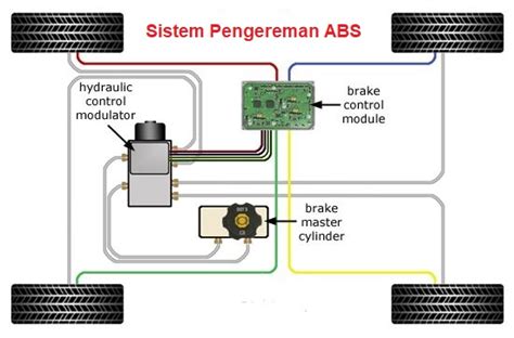
ABS Schematic Diagrams
ABS schematic diagrams provide a visual representation of the system’s components and their interconnections. These diagrams are essential for troubleshooting and understanding the flow of signals and hydraulic fluid within the system.
Basic ABS Schematic
A basic ABS schematic includes the following components:
- Wheel speed sensors
- ABS control module
- Hydraulic control unit (valves and pump)
- Accumulator
- Pump motor
- Warning light
The schematic shows the electrical connections between the components and the flow of hydraulic fluid through the system.
Detailed ABS Schematics
Detailed ABS schematics provide a more in-depth look at the system, including specific wiring diagrams and hydraulic circuit layouts. These schematics are typically used by experienced technicians for advanced diagnostics and repairs.
Detailed schematics may include:
- Wiring harness connectors and pin assignments
- Sensor and valve locations
- Hydraulic fluid flow direction
- System pressure specifications

Diagnostic Trouble Codes (DTCs)
When an issue arises within the ABS, the control module stores a Diagnostic Trouble Code (DTC) and illuminates the ABS warning light. DTCs help technicians identify the problem area and guide them through the troubleshooting process.
Common ABS DTCs include:
| DTC | Description |
|---|---|
| C0035 | Right Front Wheel Speed Sensor Circuit |
| C0040 | Left Front Wheel Speed Sensor Circuit |
| C0045 | Right Rear Wheel Speed Sensor Circuit |
| C0050 | Left Rear Wheel Speed Sensor Circuit |
| C0060 | ABS Pump Motor Circuit |
| C0065 | ABS Valve Coil Circuits |
| C0070 | ABS Control Module Internal Fault |
When diagnosing ABS issues, technicians should always consult the vehicle-specific repair manual and wiring diagrams.
ABS Troubleshooting
Troubleshooting ABS issues requires a systematic approach and an understanding of the system’s components and their functions. Common problems include:
- Wheel speed sensor faults
- Wiring harness issues
- Hydraulic valve or pump failures
- Control module malfunctions
Wheel Speed Sensor Diagnosis
Wheel speed sensors are prone to damage from road debris and corrosion. To diagnose sensor issues:
- Inspect the sensor and wiring for physical damage.
- Check the sensor’s resistance and output signal using an oscilloscope.
- Compare the sensor’s readings to the other wheels’ sensors.
- Replace the sensor if faulty.
Wiring Harness Diagnosis
Wiring harness issues can cause intermittent or complete ABS failures. To troubleshoot wiring problems:
- Visually inspect the harness for damage or corrosion.
- Check for continuity and resistance in the wires.
- Verify proper voltage supply to the components.
- Repair or replace the wiring harness as needed.
Hydraulic System Diagnosis
Hydraulic valve and pump failures can result in a loss of brake pressure or uneven braking. To diagnose hydraulic issues:
- Check the brake fluid level and condition.
- Inspect the HCU for leaks or damage.
- Test the valves and pump motor for proper operation.
- Replace faulty components as required.
Control Module Diagnosis
Control module malfunctions can cause erratic ABS behavior or complete system failure. To diagnose the control module:
- Retrieve and analyze the stored DTCs.
- Check for proper power and ground supply to the module.
- Verify the module’s communication with other vehicle systems.
- Update the module’s software if applicable.
- Replace the module if faulty.
Advanced ABS Systems
Modern vehicles often employ advanced ABS systems that integrate with other safety features, such as:
- Electronic Stability Control (ESC)
- Traction Control System (TCS)
- Automatic Emergency Braking (AEB)
- Adaptive Cruise Control (ACC)
These integrated systems use additional sensors, such as yaw rate sensors and steering angle sensors, to enhance vehicle stability and performance. Understanding the schematics and operation of these advanced systems is crucial for modern automotive technicians.
Frequently Asked Questions (FAQ)
- What are the symptoms of a faulty ABS system?
- ABS warning light illuminated on the dashboard
- Pulsating or vibrating brake pedal during heavy braking
- Longer stopping distances on slippery surfaces
-
Uneven or jerky braking performance
-
Can I drive with the ABS light on?
-
While it is possible to drive with the ABS light on, it is not recommended. A malfunction in the ABS system can compromise braking performance and safety. It is best to have the issue diagnosed and repaired as soon as possible.
-
How often should ABS components be inspected?
-
ABS components should be inspected during regular brake system maintenance, typically every 30,000 to 50,000 miles or as specified by the vehicle manufacturer. However, if you notice any symptoms of ABS malfunction, have the system inspected immediately.
-
Can ABS be retrofitted to older vehicles?
-
While it is technically possible to retrofit ABS to older vehicles, it is not a simple or cost-effective process. ABS requires specific hardware, wiring, and control modules that may not be easily integrated into older vehicle designs. It is generally more practical to upgrade to a newer vehicle equipped with ABS.
-
How does ABS affect stopping distance?
- ABS does not necessarily reduce stopping distance on dry pavement. Its primary function is to maintain steering control and stability during heavy braking, especially on wet or slippery surfaces. By preventing wheel lockup, ABS allows the driver to steer around obstacles while braking, potentially reducing the risk of accidents.
Conclusion
Understanding ABS schematics is essential for automotive technicians and enthusiasts to effectively diagnose and repair these critical safety systems. By familiarizing yourself with the components, operation, and troubleshooting techniques, you can ensure that your vehicle’s ABS remains in optimal condition, providing the safety and performance benefits it was designed to deliver.
No responses yet