Introduction to TL07x Operational Amplifiers
The TL07x series of operational amplifiers, which includes the TL071, TL072, and TL074, are widely used in various electronic circuits due to their excellent performance characteristics and versatility. These op-amps are known for their low noise, high slew rate, and wide bandwidth, making them suitable for a wide range of applications, from audio signal processing to industrial control systems.
Key Features of TL07x Op-Amps
| Feature | TL071 | TL072 | TL074 |
|---|---|---|---|
| Number of Op-Amps | 1 | 2 | 4 |
| Input Offset Voltage | 3 mV | 3 mV | 3 mV |
| Input Bias Current | 65 pA | 65 pA | 65 pA |
| Slew Rate | 13 V/μs | 13 V/μs | 13 V/μs |
| Gain-Bandwidth Product | 3 MHz | 3 MHz | 3 MHz |
| Supply Voltage Range | ±5 V to ±18 V | ±5 V to ±18 V | ±5 V to ±18 V |
| Operating Temperature Range | -40°C to +85°C | -40°C to +85°C | -40°C to +85°C |
Advantages of Using TL07x Op-Amps
- Low noise: TL07x op-amps have low input noise voltage and current, making them suitable for low-noise applications.
- High slew rate: The high slew rate of TL07x op-amps allows for fast signal processing without significant distortion.
- Wide bandwidth: The gain-bandwidth product of 3 MHz enables the use of TL07x op-amps in a variety of high-frequency applications.
- Multiple op-amps in a single package: TL072 and TL074 offer two and four op-amps, respectively, in a single package, reducing circuit size and cost.
Basic TL07x Op-Amp Circuits
1. Inverting Amplifier
An inverting amplifier using a TL07x op-amp is a simple and common circuit configuration. The gain of the amplifier is determined by the ratio of the feedback resistor (Rf) to the input resistor (Rin).
Gain = -Rf / Rin
2. Non-Inverting Amplifier
A non-inverting amplifier using a TL07x op-amp provides an output signal that is in phase with the input signal. The gain of the amplifier is determined by the ratio of the feedback resistor (Rf) to the input resistor (Rin).
Gain = 1 + (Rf / Rin)
3. Voltage Follower (Buffer)
A voltage follower, also known as a buffer, is a simple circuit that provides a high-impedance input and a low-impedance output. This circuit is useful for isolating a high-impedance source from a low-impedance load.
Gain = 1
4. Summing Amplifier
A summing amplifier using a TL07x op-amp adds multiple input signals together, with each input signal weighted by its respective input resistor. The output voltage is the inverted sum of the weighted input voltages.
Vout = -(V1 × Rf/R1 + V2 × Rf/R2 + … + Vn × Rf/Rn)
5. Differential Amplifier
A differential amplifier using a TL07x op-amp amplifies the difference between two input signals while rejecting any common-mode signals. The gain of the amplifier is determined by the ratio of the feedback resistors (Rf) to the input resistors (Rin).
Vout = (V2 – V1) × (Rf / Rin)

Advanced TL07x Op-Amp Circuits
1. Active Filters
TL07x op-amps can be used to create various types of active filters, such as low-pass, high-pass, and band-pass filters. These filters are essential in signal processing applications, allowing the desired frequency components to pass through while attenuating unwanted frequencies.
Example: Second-Order Low-Pass Filter
The cutoff frequency (fc) and quality factor (Q) of the filter are determined by the values of the resistors and capacitors:
fc = 1 / (2π √(R1 × R2 × C1 × C2))
Q = √(R1 × R2 × C1 × C2) / (R1 × C1 + R2 × C1 + R1 × C2)
2. Oscillators
TL07x op-amps can be used to create various types of oscillators, such as sine wave, square wave, and triangle wave oscillators. These oscillators generate periodic waveforms at a specific frequency, which is determined by the values of the resistors and capacitors in the circuit.
Example: Wien Bridge Oscillator
The oscillation frequency (f) is determined by the values of the resistors and capacitors:
f = 1 / (2π × R × C)
3. Comparators
TL07x op-amps can be used as comparators, which compare an input signal with a reference voltage and provide a digital output based on the comparison result. Comparators are essential in various applications, such as analog-to-digital converters and level detectors.
Example: Simple Comparator
When Vin > Vref, Vout = +Vcc
When Vin < Vref, Vout = -Vcc
4. Precision Rectifiers
TL07x op-amps can be used to create precision rectifiers, which convert an AC input signal into a DC output signal. Precision rectifiers are useful in various applications, such as AC-to-DC power supplies and signal conditioning circuits.
Example: Full-Wave Precision Rectifier
The output voltage (Vout) is the absolute value of the input voltage (Vin), with a small voltage drop due to the diodes:
Vout = |Vin| – 2 × Vdiode

TL07x Op-Amp Application Examples
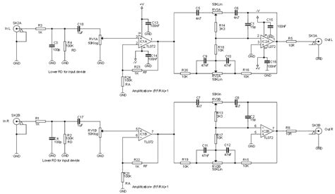
1. Audio preamplifier
TL07x op-amps are commonly used in audio preamplifiers due to their low noise and high slew rate. A typical audio preamplifier circuit using a TL07x op-amp consists of an input stage, a volume control, and an output buffer.
2. Temperature Controller
TL07x op-amps can be used in temperature control systems, where they amplify the signal from a temperature sensor and compare it with a reference voltage to control a heating or cooling element.
3. Voltage Regulator
TL07x op-amps can be used to create linear voltage regulators, which provide a stable output voltage despite variations in the input voltage or load current.
4. Current-to-Voltage Converter
TL07x op-amps can be used to convert a current signal into a voltage signal, which is useful in various sensor applications, such as photodiodes and current-output temperature sensors.

Frequently Asked Questions (FAQ)
-
What is the difference between TL071, TL072, and TL074 op-amps?
The main difference between these op-amps is the number of op-amps in a single package. TL071 has one op-amp, TL072 has two op-amps, and TL074 has four op-amps. The performance characteristics of the individual op-amps are the same across the three models. -
Can TL07x op-amps be used with single-supply voltages?
Yes, TL07x op-amps can be used with single-supply voltages, but the input and output voltage ranges will be limited to the range between the negative supply voltage (usually ground) and the positive supply voltage minus a small voltage drop. -
What is the maximum supply voltage for TL07x op-amps?
The maximum supply voltage for TL07x op-amps is ±18 V. However, it is essential to ensure that the power dissipation of the op-amp does not exceed its maximum rating, which is typically 680 mW. -
How can I reduce the noise in my TL07x op-amp circuit?
To reduce noise in your TL07x op-amp circuit, consider the following tips: - Use a low-noise power supply with proper decoupling capacitors.
- Minimize the length of high-impedance traces and keep them away from noise sources.
- Use shielded cables for sensitive signal paths.
-
Add a small capacitor (e.g., 10-100 pF) in parallel with the feedback resistor to reduce high-frequency noise.
-
Can I replace a TL07x op-amp with another op-amp in my circuit?
In most cases, you can replace a TL07x op-amp with another op-amp that has similar performance characteristics. However, it is essential to consider the specific requirements of your circuit, such as supply voltage range, input/output voltage range, slew rate, and noise performance, to ensure proper operation.
Conclusion
TL07x op-amps are versatile and high-performance components that find applications in a wide range of electronic circuits. By understanding the basic principles and common circuit configurations, designers can effectively utilize these op-amps to create efficient and reliable systems. Whether in audio signal processing, industrial control, or sensor interfacing, TL07x op-amps provide the necessary building blocks for successful circuit designs.
No responses yet