Introduction to Gerber Formats
Gerber formats are a set of file formats used in the electronic design automation (EDA) industry for the design and manufacture of printed circuit boards (PCBs). These formats were originally developed by the Gerber Systems Corp., which was later acquired by Ucamco. Gerber files contain information about the various layers of a PCB, including the copper traces, solder mask, silkscreen, and drill holes.
History of Gerber Formats
The Gerber format was first introduced in the 1960s as a means of controlling photoplotter machines used for creating PCB Artwork. Over time, the format evolved to accommodate the increasing complexity of PCB designs and the introduction of new manufacturing technologies.
Key milestones in the development of Gerber formats include:
| Year | Milestone |
|---|---|
| 1960s | Introduction of the original Gerber format |
| 1980s | Development of the Extended Gerber format (RS-274X) |
| 1998 | Establishment of the Gerber Format Specification (GFS) |
| 2013 | Introduction of the Gerber X2 format |
Types of Gerber Files
A complete set of Gerber files for a PCB typically includes the following:
Copper Layer Files (GTL/GBL)
These files represent the top (GTL) and bottom (GBL) copper layers of the PCB, containing information about the traces, pads, and vias.
Solder Mask Files (GTS/GBS)
The top (GTS) and bottom (GBS) solder mask files define the areas of the PCB that will be covered by solder resist, protecting the copper traces from accidental shorts and providing insulation.
Silkscreen Files (GTO/GBO)
The top (GTO) and bottom (GBO) silkscreen files contain the text and graphics that will be printed on the PCB for component identification and labeling.
Solder Paste Files (GTP/GBP)
These files define the areas where solder paste will be applied for surface mount components during the assembly process.
Drill Files (DRL/TXT)
The drill files contain information about the location, size, and type of holes to be drilled in the PCB for through-hole components and vias.

Gerber File Structure
A Gerber file consists of a series of commands that describe the various features of the PCB layer. These commands are represented using a combination of ASCII characters and numerical parameters.
Aperture Definitions
Apertures are the basic building blocks of Gerber files, representing the shapes used to create the PCB features. Common aperture types include:
- Circles
- Rectangles
- Obround
- Polygons
Apertures are defined using the AD command, followed by the aperture number, type, and dimensions.
Example:
%ADD10C,0.5*%
This command defines aperture number 10 as a circle with a diameter of 0.5 units.
Aperture Macros
Aperture macros are used to define complex or custom aperture shapes that cannot be represented using standard aperture types. Macros are defined using the AM command, followed by the macro name and a series of primitive shapes and operations.
Example:
%AMDONUT*
1,1,0.5,0,0,0.25,0*
1,1,0.25,0,0,0*
%
This macro defines a donut-shaped aperture consisting of two concentric circles.
D-Codes
D-codes are used to select a previously defined aperture for drawing operations. The D01 command is used to move the aperture to a new location, while the D02 command is used to create a flash (exposure) at the current location.
Example:
D10*
X1000Y1000D02*
X2000Y2000D01*
This sequence selects aperture number 10, moves to the coordinates (1000, 1000), and then creates a line to (2000, 2000).

Gerber File Creation
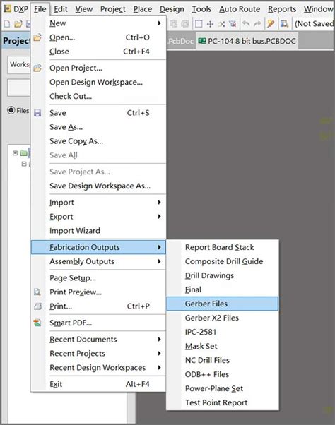
Gerber files are typically generated by PCB design software as part of the output process. Most modern PCB design tools, such as Altium Designer, KiCad, and Eagle, have built-in support for exporting Gerber files.
When creating Gerber files, it is important to adhere to the following best practices:
- Use a consistent naming convention for the files, clearly identifying the layer and purpose of each file.
- Ensure that all files are generated using the same units (e.g., inches or millimeters) and coordinate system.
- Include a readme file or fabrication drawing that provides additional information about the PCB, such as the board thickness, material, and finish requirements.
- Verify the Gerber files using a Gerber viewer or DFM (Design for Manufacturability) tool to check for errors or potential manufacturing issues.

Gerber File Viewing and Analysis
Gerber files can be viewed and analyzed using specialized software tools known as Gerber viewers. These tools allow users to inspect the various layers of the PCB, measure distances and angles, and check for potential manufacturing issues.
Some popular Gerber viewers include:
- GerbView (included with KiCad)
- ViewMate (by Pentalogix)
- CAM350 (by DownStream Technologies)
- GC-Prevue (by GraphiCode)
In addition to viewing Gerber files, many of these tools also offer DFM analysis capabilities, helping to identify potential problems such as:
- Acid traps
- Copper slivers
- Soldermask slivers
- Silkscreen over pads
- Insufficient clearances
By addressing these issues before sending the Gerber files to a manufacturer, designers can help ensure a smoother and more reliable production process.
Gerber X2 Format
In 2013, Ucamco introduced the Gerber X2 format as an extension to the existing RS-274X format. Gerber X2 adds new features and capabilities designed to improve the efficiency and reliability of PCB fabrication and assembly.
Key features of the Gerber X2 format include:
- Embedded attributes: X2 allows for the inclusion of additional information within the Gerber files, such as part numbers, component locations, and layer types.
- Nested step and repeat: This feature enables the efficient representation of repeated patterns or structures within the PCB design.
- Pads and vias: X2 introduces new commands for defining pads and vias, simplifying the creation of complex pad shapes and via structures.
- Backdrilling: The format supports the specification of backdrilling requirements for vias, helping to improve signal integrity and reduce EMI.
Despite these advantages, adoption of the Gerber X2 format has been relatively slow, with many designers and manufacturers still relying on the older RS-274X format.
Frequently Asked Questions (FAQ)
1. What is the difference between Gerber and ODB++ formats?
Gerber and ODB++ are both file formats used for PCB design and manufacturing, but they have some key differences. Gerber is an open, ASCII-based format that represents each PCB layer as a separate file. ODB++, on the other hand, is a proprietary format developed by Mentor Graphics that stores all PCB data in a single, binary file. ODB++ includes additional information not found in Gerber files, such as netlist and component data.
2. Can I view Gerber files without specialized software?
While it is possible to open Gerber files in a text editor, the contents will appear as a series of cryptic commands and coordinates. To properly view and interpret Gerber files, it is necessary to use a dedicated Gerber viewer or PCB design software with built-in Gerber support.
3. What is the difference between RS-274D and RS-274X Gerber formats?
RS-274D, also known as Standard Gerber, is an older version of the Gerber format that has largely been superseded by RS-274X, or Extended Gerber. The main differences between the two formats are:
- RS-274X supports aperture macros for defining custom shapes, while RS-274D does not.
- RS-274X includes additional commands for specifying polarity, image rotation, and scaling.
- RS-274X allows for the use of decimal coordinates, while RS-274D uses integer coordinates only.
In general, RS-274X is more flexible and powerful than RS-274D, and is the preferred format for modern PCB design and manufacturing.
4. How do I ensure that my Gerber files are compatible with a specific PCB manufacturer?
Most PCB manufacturers will provide a set of Gerber file requirements or guidelines on their website or upon request. These requirements may include specific naming conventions, file formats, and layer specifications. By following these guidelines and communicating openly with the manufacturer, you can help ensure that your Gerber files are compatible and ready for production.
5. What are some common issues encountered when working with Gerber files?
Some common issues that can arise when working with Gerber files include:
- Incorrect file naming or layer designation
- Discrepancies in units or coordinate systems between files
- Missing or incomplete files
- Aperture or macro definition errors
- Insufficient clearances or spacing between features
- Incompatibility with manufacturer specifications
To minimize these issues, it is important to carefully review and verify your Gerber files before submitting them for manufacturing, and to work closely with your PCB manufacturer to address any concerns or questions that may arise.
Conclusion
Gerber formats play a critical role in the design and manufacture of printed circuit boards, providing a standardized way to represent the various layers and features of a PCB. By understanding the structure and capabilities of Gerber files, designers can create accurate and reliable PCB designs that are ready for production.
As PCB technology continues to evolve, so too do the Gerber formats that support it. The introduction of the Gerber X2 format, for example, has brought new capabilities and efficiencies to the PCB fabrication process, while still maintaining backwards compatibility with existing workflows.
Ultimately, the success of any PCB project depends on effective communication and collaboration between designers, manufacturers, and other stakeholders. By working together to ensure the accuracy and integrity of Gerber files, these teams can help bring innovative and reliable electronic products to market faster and more efficiently than ever before.
No responses yet