Understanding Soldering Temperatures and PCB Durability
When it comes to assembling electronic components on a printed circuit board (PCB), soldering is a crucial process. In recent years, the industry has shifted towards lead-free soldering to comply with environmental regulations and ensure the safety of consumers and workers. However, lead-free soldering requires higher temperatures compared to traditional lead-based soldering, which raises concerns about the durability of PCBs subjected to these elevated temperatures. In this article, we will explore the factors that influence how often a PCB can withstand lead-free soldering temperatures and provide guidance on maximizing the longevity of your PCBs.
What is Lead-free Soldering?
Lead-free soldering is a process that uses solder alloys without lead, typically consisting of tin, silver, and copper. The most common lead-free solder alloy is SAC305, which contains 96.5% tin, 3% silver, and 0.5% copper. Lead-free soldering was introduced to address the health and environmental concerns associated with lead exposure.
Lead-free Soldering Temperature Range
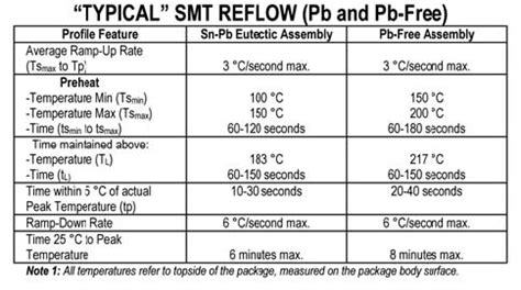
Lead-free soldering requires higher temperatures compared to traditional lead-based soldering. The typical temperature range for lead-free soldering is between 240°C and 260°C (464°F to 500°F), with the most common temperature being around 250°C (482°F). In contrast, lead-based soldering typically occurs at temperatures between 180°C and 220°C (356°F to 428°F).
Factors Affecting PCB Durability during Soldering
Several factors influence how well a PCB can withstand repeated exposure to lead-free soldering temperatures:
1. PCB Material
The choice of PCB material plays a significant role in its ability to withstand high soldering temperatures. The most common PCB materials are:
-
FR-4: A glass-reinforced epoxy laminate, FR-4 is the most widely used PCB material. It has a glass transition temperature (Tg) of around 135°C (275°F) and can withstand lead-free soldering temperatures for a limited number of cycles.
-
High-Tg FR-4: This material has a higher glass transition temperature, typically above 170°C (338°F), making it more suitable for repeated exposure to lead-free soldering temperatures.
-
Polyimide: With a glass transition temperature above 250°C (482°F), Polyimide PCBs are ideal for applications that require frequent soldering at high temperatures.
2. PCB Thickness
Thicker PCBs are generally more resilient to thermal stress caused by soldering. A standard 1.6 mm (0.063 inch) thick PCB can withstand more soldering cycles compared to a thinner board. However, thicker boards may present challenges in terms of design and manufacturing constraints.
3. Copper Thickness
The thickness of the copper traces on a PCB also influences its ability to withstand multiple soldering cycles. Thicker copper traces, such as 2 oz. or 3 oz. copper, can dissipate heat more effectively and reduce thermal stress on the board compared to thinner traces like 1 oz. copper.
4. Soldering Technique
The soldering technique employed can impact the PCB’s durability. Hand soldering, which typically involves applying heat for longer durations, can cause more thermal stress on the board compared to machine soldering processes like wave soldering or reflow soldering, which have more precise temperature control and shorter dwell times.

Maximizing PCB Durability for Repeated Soldering
To ensure that your PCBs can withstand multiple lead-free soldering cycles, consider the following guidelines:
-
Choose a High-Temperature PCB material like High-Tg FR-4 or polyimide, especially if frequent soldering is anticipated.
-
Opt for thicker PCBs, such as 1.6 mm or greater, to improve thermal resilience.
-
Use thicker copper traces, like 2 oz. or 3 oz. copper, to enhance heat dissipation and reduce thermal stress.
-
Employ machine soldering processes, such as wave soldering or reflow soldering, to minimize thermal exposure time and ensure precise temperature control.
-
Implement a robust thermal management strategy, including the use of thermal reliefs, copper pours, and appropriate component placement to distribute heat evenly across the PCB.

Estimating the Number of Soldering Cycles a PCB Can Withstand
The number of times a PCB can be raised to lead-free soldering temperatures depends on various factors, as discussed earlier. However, as a general guideline, the following table provides an estimate of the number of soldering cycles a PCB can withstand based on its material and thickness:
| PCB Material | Thickness (mm) | Estimated Soldering Cycles |
|---|---|---|
| FR-4 | 1.6 | 3-5 |
| High-Tg FR-4 | 1.6 | 5-10 |
| Polyimide | 1.6 | 10-20 |
Note: These estimates are based on typical lead-free soldering temperatures and assume proper thermal management techniques are employed. Actual results may vary depending on specific manufacturing processes and design factors.

Frequently Asked Questions (FAQ)
-
Q: Can I use lead-based solder instead of lead-free solder to reduce thermal stress on my PCBs?
A: While lead-based solder has a lower melting point and requires lower soldering temperatures, it is not recommended due to environmental and health concerns. Many countries have regulations restricting the use of lead in electronic products. -
Q: How can I tell if my PCB has been damaged by repeated exposure to high soldering temperatures?
A: Signs of thermal damage on a PCB include discoloration, warping, delamination, and lifted or damaged copper traces. If you notice any of these symptoms, it may indicate that the PCB has been subjected to excessive thermal stress. -
Q: Can I mix different PCB materials in the same design to improve thermal resilience in specific areas?
A: Yes, it is possible to use different PCB materials in the same design, a technique known as hybrid construction. For example, you could use a high-temperature material like polyimide in areas that will be subjected to frequent soldering, while using standard FR-4 in other areas to reduce costs. -
Q: Are there any alternative soldering methods that can help reduce thermal stress on PCBs?
A: Vapor phase soldering is an alternative method that uses a heated vapor to transfer heat to the PCB and components, providing a more uniform and controlled thermal environment. This method can help reduce thermal stress on the PCB compared to conventional soldering techniques. -
Q: How does the component type and packaging affect a PCB’s ability to withstand multiple soldering cycles?
A: The type of components used on a PCB and their packaging can influence the board’s thermal resilience. Surface mount devices (SMDs) generally have better thermal characteristics compared to through-hole components. Additionally, components with larger packages or heat-sinking features can help dissipate heat more effectively, reducing thermal stress on the PCB.
Conclusion
The ability of a PCB to withstand repeated exposure to lead-free soldering temperatures depends on several factors, including the PCB material, thickness, copper thickness, and soldering technique employed. By selecting high-temperature materials, opting for thicker boards and copper traces, and implementing proper thermal management strategies, you can maximize the durability of your PCBs and ensure they can withstand multiple soldering cycles.
When designing PCBs for applications that require frequent soldering, it is essential to consider the thermal requirements early in the design process and work closely with your PCB manufacturer to select the most appropriate materials and manufacturing techniques. By following best practices and understanding the factors that influence PCB durability, you can create robust and reliable electronic assemblies that can withstand the rigors of lead-free soldering.
No responses yet