Understanding PCB tolerances and Their Importance
Printed Circuit Boards (PCBs) are essential components in modern electronics, serving as the foundation for interconnecting various electronic components. To ensure proper functionality and reliability of the final product, it is crucial to understand and adhere to the tolerances specified during the PCB manufacturing process. PCB Tolerances refer to the acceptable variations in dimensions, spacing, and other parameters that can occur during fabrication without compromising the board’s performance.
Why are PCB Tolerances Critical?
PCB tolerances play a vital role in several aspects of the manufacturing process and the final product’s performance:
-
Manufacturability: Adhering to specified tolerances ensures that the PCB can be manufactured consistently and reliably, reducing the likelihood of defects and production delays.
-
Component Compatibility: Proper tolerances guarantee that electronic components can be accurately placed and soldered onto the PCB, ensuring proper connections and functionality.
-
Signal Integrity: Maintaining precise tolerances for trace widths, spacing, and other parameters helps minimize signal interference, crosstalk, and impedance mismatches, which can negatively impact the board’s performance.
-
Reliability: Adhering to tolerances reduces the risk of short circuits, open circuits, and other issues that can lead to device failures or malfunctions.
Types of PCB Tolerances
There are several types of tolerances that must be considered during the PCB design and manufacturing process:
1. Dimensional Tolerances
Dimensional tolerances refer to the acceptable variations in the physical dimensions of the PCB, such as length, width, and thickness. These tolerances are typically specified in millimeters (mm) or inches (in) and can vary depending on the PCB material, manufacturing process, and the specific requirements of the application.
| Dimension | Tolerance |
|---|---|
| Length | ±0.2 mm |
| Width | ±0.2 mm |
| Thickness | ±10% |
2. Hole Tolerances
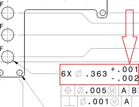
Hole tolerances define the acceptable variations in the diameter and position of drilled holes on the PCB. These holes are used for mounting components, vias, and connectors. Maintaining precise hole tolerances is essential for ensuring proper component fit and alignment. Hole tolerances are typically specified in millimeters or inches.
| Hole Type | Diameter Tolerance | Position Tolerance |
|---|---|---|
| Standard Holes | ±0.1 mm | ±0.1 mm |
| Plated Through Holes | ±0.05 mm | ±0.05 mm |
3. Trace Tolerances
Trace tolerances refer to the acceptable variations in the width and spacing of the conductive traces on the PCB. These tolerances are critical for maintaining signal integrity and preventing short circuits or crosstalk between adjacent traces. Trace tolerances are typically specified in millimeters or mils (1 mil = 0.001 inches).
| Trace Parameter | Tolerance |
|---|---|
| Trace Width | ±0.1 mm |
| Trace Spacing | ±0.1 mm |
4. Solder Mask Tolerances
Solder mask tolerances define the acceptable variations in the alignment and coverage of the solder mask layer on the PCB. The solder mask is a protective coating that covers the copper traces, preventing short circuits and providing insulation. Solder mask tolerances are typically specified in millimeters or mils.
| Solder Mask Parameter | Tolerance |
|---|---|
| Solder Mask Alignment | ±0.1 mm |
| Solder Mask Coverage | ±0.05 mm |
5. Silkscreen Tolerances
Silkscreen tolerances refer to the acceptable variations in the alignment and legibility of the silkscreen layer on the PCB. The silkscreen layer contains text, logos, and other markings that aid in the assembly and identification of components. Silkscreen tolerances are typically specified in millimeters or mils.
| Silkscreen Parameter | Tolerance |
|---|---|
| Silkscreen Alignment | ±0.2 mm |
| Text Legibility | ±0.1 mm |

Factors Affecting PCB Tolerances
Several factors can influence the achievable tolerances during the PCB manufacturing process:
-
Manufacturing Process: Different PCB manufacturing processes, such as etching, drilling, and plating, have their own inherent limitations and tolerances. The choice of manufacturing process can impact the overall tolerances of the final product.
-
PCB Material: The type of PCB material used, such as FR-4, high-frequency laminates, or flexible substrates, can affect the achievable tolerances. Some materials may have more stringent tolerance requirements or limitations compared to others.
-
Board Complexity: The complexity of the PCB design, including the number of layers, component density, and trace routing, can influence the tolerances that can be maintained during manufacturing. More complex designs may require tighter tolerances to ensure proper functionality.
-
Manufacturing Equipment: The precision and capabilities of the manufacturing equipment used, such as etching machines, drills, and plating equipment, can impact the achievable tolerances. Investing in high-quality and well-maintained equipment can help maintain tighter tolerances.
-
Quality Control Processes: Implementing robust quality control processes, including inspections, measurements, and testing, can help identify and correct any deviations from the specified tolerances during the manufacturing process. Effective quality control ensures that the final product meets the desired tolerances.

Designing for PCB Tolerances
To ensure a successful PCB design that can be manufactured reliably and within specified tolerances, designers should consider the following guidelines:
-
Communicate with the Manufacturer: Engage in open communication with the PCB manufacturer to understand their capabilities, limitations, and recommended tolerances. Discuss any specific requirements or constraints early in the design process to avoid potential issues later on.
-
Follow Design Guidelines: Adhere to the design guidelines provided by the PCB manufacturer or industry standards, such as the IPC (Association Connecting Electronics Industries) standards. These guidelines outline recommended practices for trace widths, spacing, hole sizes, and other parameters to ensure manufacturability and reliability.
-
Use Appropriate Design Tools: Utilize PCB design software that supports the specification and verification of tolerances. These tools can help identify potential tolerance issues during the design phase, allowing for necessary adjustments before manufacturing.
-
Consider Manufacturing Constraints: Be aware of the manufacturing constraints associated with different PCB fabrication processes. For example, certain processes may have limitations on minimum trace widths, hole sizes, or spacing. Design your PCB with these constraints in mind to avoid manufacturability issues.
-
Perform Design Reviews: Conduct thorough design reviews to catch any tolerance-related issues early in the development process. Involve experienced PCB designers, manufacturers, and other stakeholders to review the design and provide feedback on potential tolerance concerns.
-
Allow for Adequate Margins: Incorporate appropriate margins and clearances in your PCB design to accommodate potential variations in manufacturing tolerances. Providing adequate spacing between components, traces, and other features can help mitigate the impact of tolerance deviations.
-
Prototype and Test: Before mass production, fabricate prototypes of your PCB design and perform thorough testing to verify that the manufactured boards meet the specified tolerances and functional requirements. Testing can help identify any issues related to tolerances and allow for necessary design refinements.

Frequently Asked Questions (FAQ)
-
What are the consequences of not adhering to PCB tolerances?
Not adhering to PCB tolerances can lead to various issues, such as component misalignment, short circuits, signal integrity problems, and reduced reliability. These issues can result in device malfunctions, production delays, and increased costs associated with rework or scrap. -
How can I ensure that my PCB design meets the required tolerances?
To ensure that your PCB design meets the required tolerances, follow these steps: - Communicate with the PCB manufacturer to understand their capabilities and recommended tolerances.
- Adhere to industry standards and design guidelines for PCB layout and tolerances.
- Use appropriate PCB design software that supports tolerance specification and verification.
- Perform thorough design reviews to catch any tolerance-related issues early in the development process.
- Allow for adequate margins and clearances in your PCB design to accommodate potential variations.
-
Prototype and test your PCB design to verify that the manufactured boards meet the specified tolerances.
-
What should I do if my PCB design requires tighter tolerances than the manufacturer’s standard capabilities?
If your PCB design requires tighter tolerances than the manufacturer’s standard capabilities, discuss your specific requirements with the manufacturer. They may be able to accommodate tighter tolerances through specialized processes or equipment. However, be prepared for potential increases in cost and lead time associated with non-standard tolerances. -
Can PCB tolerances impact the cost of manufacturing?
Yes, PCB tolerances can impact the cost of manufacturing. Tighter tolerances often require more precise manufacturing processes, specialized equipment, and additional quality control measures, which can increase the overall cost of production. It is important to strike a balance between the required tolerances and cost-effectiveness. -
Are there any industry standards that specify PCB tolerances?
Yes, there are several industry standards that provide guidelines and specifications for PCB tolerances. The most widely recognized standards are those developed by the IPC (Association Connecting Electronics Industries), such as IPC-6012 for rigid printed boards and IPC-6013 for flexible printed boards. These standards outline recommended tolerances for various aspects of PCB manufacturing.
Conclusion
Understanding and adhering to PCB tolerances is crucial for ensuring the manufacturability, reliability, and performance of printed circuit boards. Tolerances encompass various aspects of PCB design, including dimensions, holes, traces, solder mask, and silkscreen. Several factors, such as the manufacturing process, PCB material, board complexity, manufacturing equipment, and quality control processes, can influence the achievable tolerances.
To design for PCB tolerances effectively, designers should communicate with the manufacturer, follow design guidelines, use appropriate design tools, consider manufacturing constraints, perform design reviews, allow for adequate margins, and prototype and test their designs. By prioritizing PCB tolerances throughout the design and manufacturing process, designers can minimize the risk of issues, reduce costs, and ensure the successful production of high-quality printed circuit boards.
No responses yet