Introduction to Circuit Board Components
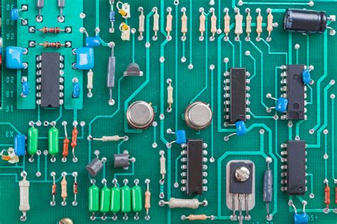
A circuit board, also known as a printed circuit board (PCB), is the foundation of modern electronic devices. It is a flat board made of insulating material, such as fiberglass or plastic, with conductive pathways etched or printed onto its surface. These pathways, called traces, connect various electronic components to form a functional circuit. Understanding the different types of components found on a circuit board is essential for anyone working with electronics, whether you are a hobbyist, a student, or a professional.
In this comprehensive guide, we will explore the most common circuit board components, their functions, and how to identify them. By the end of this article, you will have a solid foundation in recognizing and understanding the various components that make up a circuit board.
Types of Circuit Board Components
1. Resistors
1.1 What are Resistors?
Resistors are passive components that oppose the flow of electric current in a circuit. They are used to control voltage levels, limit current, and divide voltages. Resistors are characterized by their resistance value, measured in ohms (Ω), and their power rating, measured in watts (W).
1.2 Identifying Resistors
Resistors come in various sizes and shapes, but the most common type is the axial lead resistor. These resistors have a cylindrical body with two leads extending from each end. The resistance value is typically indicated by a color code printed on the body of the resistor.
The standard resistor color code consists of four or five colored bands:
- The first two bands represent the first two digits of the resistance value.
- The third band represents the multiplier (number of zeros following the first two digits).
- The fourth band (if present) represents the tolerance, or the acceptable range of variation in the resistance value.
- The fifth band (if present) represents the temperature coefficient, which indicates how much the resistance changes with temperature.
Here is a table of the resistor color code:
| Color | Digit | Multiplier | Tolerance | Temperature Coefficient |
|---|---|---|---|---|
| Black | 0 | 1 | – | – |
| Brown | 1 | 10 | ±1% | 100 ppm/°C |
| Red | 2 | 100 | ±2% | 50 ppm/°C |
| Orange | 3 | 1,000 | – | 15 ppm/°C |
| Yellow | 4 | 10,000 | – | 25 ppm/°C |
| Green | 5 | 100,000 | ±0.5% | – |
| Blue | 6 | 1,000,000 | ±0.25% | 10 ppm/°C |
| Violet | 7 | – | ±0.1% | 5 ppm/°C |
| Gray | 8 | – | ±0.05% | – |
| White | 9 | – | – | – |
| Gold | – | 0.1 | ±5% | – |
| Silver | – | 0.01 | ±10% | – |
For example, a resistor with the color code yellow, violet, orange, gold would have a resistance value of 47,000 Ω (47 kΩ) with a tolerance of ±5%.
2. Capacitors
2.1 What are Capacitors?
Capacitors are passive components that store electrical energy in an electric field. They are used for filtering, coupling, decoupling, and energy storage in electronic circuits. Capacitors are characterized by their capacitance value, measured in farads (F), and their voltage rating, which indicates the maximum voltage they can withstand without breaking down.
2.2 Identifying Capacitors
Capacitors come in various shapes and sizes, depending on their type and application. Some common types of capacitors include:
-
Ceramic Capacitors: These are small, disc-shaped capacitors with a ceramic dielectric. They are non-polarized and typically used for high-frequency applications and decoupling.
-
Electrolytic Capacitors: These are polarized capacitors with a larger capacitance value than ceramic capacitors. They have a cylindrical shape with two leads and are often used for power supply filtering and low-frequency coupling. Electrolytic capacitors must be connected with the correct polarity, as indicated by the ‘+’ and ‘-‘ signs on the body.
-
Tantalum Capacitors: These are polarized capacitors with a tantalum oxide dielectric. They have a higher capacitance density than electrolytic capacitors and are often used in miniature electronic devices.
-
Film Capacitors: These are non-polarized capacitors with a plastic film dielectric. They are available in various shapes and sizes and are used for a wide range of applications, including filtering, coupling, and energy storage.
Capacitor values are often printed on the body of the component using a numerical code. For smaller capacitors, the code consists of three digits, where the first two digits represent the significant figures, and the third digit represents the multiplier (number of zeros following the significant figures). The value is typically given in picofarads (pF).
For example, a ceramic capacitor with the code “104” would have a capacitance value of 10 × 10^4 pF, or 100,000 pF (0.1 µF).
Larger capacitors, such as electrolytic and tantalum capacitors, often have their capacitance and voltage ratings printed directly on the body.
3. Inductors
3.1 What are Inductors?
Inductors are passive components that store energy in a magnetic field when electric current flows through them. They are used for filtering, energy storage, and creating magnetic fields in electronic circuits. Inductors are characterized by their inductance value, measured in henries (H), and their current rating, which indicates the maximum current they can handle without saturating.
3.2 Identifying Inductors
Inductors come in various shapes and sizes, depending on their application and inductance value. Some common types of inductors include:
-
Axial Lead Inductors: These inductors have a cylindrical body with two leads extending from each end. They are often used in low-frequency applications and power supply filters.
-
Surface Mount Inductors: These inductors are designed for surface mount technology (SMT) and have a rectangular or square shape with no leads. They are used in high-frequency applications and miniature electronic devices.
-
Toroidal Inductors: These inductors have a donut-shaped core with wire wrapped around it. They have a high inductance value and are often used in power supply filters and transformers.
Inductor values are typically printed on the body of the component, either directly or using a numerical code similar to that used for resistors.
4. Diodes
4.1 What are Diodes?
Diodes are semiconductor devices that allow current to flow in only one direction. They are used for rectification, voltage regulation, and protection against reverse polarity in electronic circuits. Diodes are characterized by their forward voltage drop, which is the voltage required for the diode to conduct current, and their maximum reverse voltage, which is the highest voltage the diode can withstand in the reverse direction without breaking down.
4.2 Identifying Diodes
Diodes come in various shapes and sizes, depending on their type and application. Some common types of diodes include:
-
Rectifier Diodes: These diodes are used for converting alternating current (AC) to direct current (DC). They have a high current capacity and are often used in power supply circuits.
-
Signal Diodes: These diodes are used for small-signal applications, such as switching and clamping. They have a lower current capacity than rectifier diodes and are often used in logic circuits.
-
Zener Diodes: These diodes are designed to operate in the reverse breakdown region and maintain a constant voltage across their terminals. They are used for voltage regulation and reference in electronic circuits.
-
Light-Emitting Diodes (LEDs): These diodes emit light when current flows through them. They are used for indicators, displays, and lighting applications.
Diodes typically have a cylindrical body with two leads, one for the anode (positive terminal) and one for the cathode (negative terminal). The cathode is often marked with a stripe or band on the body of the diode.
5. Transistors
5.1 What are Transistors?
Transistors are semiconductor devices that can amplify or switch electronic signals. They are the building blocks of modern electronic circuits and are used in a wide range of applications, including amplifiers, oscillators, and digital logic circuits. Transistors are characterized by their type (bipolar or field-effect), their gain (the ratio of output current to input current), and their maximum voltage and current ratings.
5.2 Identifying Transistors
Transistors come in various shapes and sizes, depending on their type and application. Some common types of transistors include:
-
Bipolar Junction Transistors (BJTs): These transistors have three terminals: the emitter, the base, and the collector. They are used for amplification and switching in analog and digital circuits. BJTs are available in two types: NPN and PNP, which refer to the arrangement of the semiconductor layers.
-
Field-Effect Transistors (FETs): These transistors have three terminals: the source, the gate, and the drain. They are used for amplification and switching in analog and digital circuits. FETs are available in two types: junction FETs (JFETs) and metal-oxide-semiconductor FETs (MOSFETs).
Transistors often have a small, rectangular body with three leads. The lead arrangement and pinout depend on the type and package of the transistor. It is essential to refer to the device datasheet to identify the correct pinout and maximum ratings.
6. Integrated Circuits
6.1 What are Integrated Circuits?
Integrated circuits (ICs) are miniature electronic circuits that contain multiple components, such as transistors, diodes, resistors, and capacitors, fabricated on a single semiconductor substrate. ICs are used to perform specific functions, such as amplification, signal processing, memory storage, and digital logic operations. They are the foundation of modern electronic devices and have revolutionized the electronics industry by enabling the development of smaller, faster, and more efficient systems.
6.2 Identifying Integrated Circuits
Integrated circuits come in various packages, depending on their complexity and the number of pins they require. Some common IC packages include:
-
Dual In-line Package (DIP): These ICs have a rectangular body with two rows of pins extending from each side. They are often used in through-hole circuit boards and are easy to handle and replace.
-
Small Outline Integrated Circuit (SOIC): These ICs have a rectangular body with two rows of pins extending from each side, similar to DIP packages, but with a smaller footprint. They are used in surface mount circuit boards and are more compact than DIP packages.
-
Quad Flat Package (QFP): These ICs have a square or rectangular body with pins extending from all four sides. They are used in surface mount circuit boards and offer a higher pin count than SOIC packages.
-
Ball Grid Array (BGA): These ICs have a square or rectangular body with an array of solder balls on the bottom surface. They are used in high-density surface mount circuit boards and offer the highest pin count and smallest footprint among IC packages.
ICs are identified by their part number, which is typically printed on the top surface of the package. The part number includes information about the device type, manufacturer, and specific function. It is essential to refer to the device datasheet to determine the pinout, electrical characteristics, and application notes for the IC.

Frequently Asked Questions (FAQ)
-
What is the difference between a resistor and a capacitor?
A resistor opposes the flow of electric current, while a capacitor stores electrical energy in an electric field. Resistors are used to control voltage levels and limit current, while capacitors are used for filtering, coupling, and decoupling in electronic circuits. -
How do I determine the value of a resistor using the color code?
The resistor color code consists of four or five colored bands that indicate the resistance value and tolerance. The first two bands represent the first two digits of the value, the third band represents the multiplier, and the fourth band (if present) represents the tolerance. Refer to the resistor color code table to determine the value of each band. -
What is the purpose of a diode in an electronic circuit?
A diode allows current to flow in only one direction, which is useful for rectification (converting AC to DC), voltage regulation, and protection against reverse polarity. Diodes are also used in specific applications, such as light-emitting diodes (LEDs) for indicators and displays. -
What is the difference between a bipolar junction transistor (BJT) and a field-effect transistor (FET)?
BJTs and FETs are both used for amplification and switching in electronic circuits. However, BJTs are current-controlled devices, meaning that a small current applied to the base terminal controls a larger current flowing between the emitter and collector terminals. FETs, on the other hand, are voltage-controlled devices, where a voltage applied to the gate terminal controls the current flowing between the source and drain terminals. -
What are the advantages of using integrated circuits (ICs) in electronic devices?
Integrated circuits offer several advantages over discrete components, including: - Miniaturization: ICs contain multiple components fabricated on a single semiconductor substrate, allowing for smaller and more compact electronic devices.
- Increased reliability: Since the components in an IC are fabricated together, there are fewer interconnections and potential points of failure compared to circuits built with discrete components.
- Lower cost: Mass production of ICs leads to lower manufacturing costs compared to assembling circuits with individual components.
- Improved performance: ICs can operate at higher speeds and with lower power consumption than equivalent circuits built with discrete components.

Conclusion
Understanding the different types of components found on a circuit board is crucial for anyone working with electronics. This comprehensive guide has covered the most common circuit board components, including resistors, capacitors, inductors, diodes, transistors, and integrated circuits. By learning how to identify these components and understanding their functions, you will be better equipped to design, troubleshoot, and repair electronic circuits.
Remember to always refer to the component datasheets for specific information on pinouts, electrical characteristics, and application notes. With practice and experience, you will develop a keen eye for recognizing circuit board components and understanding their roles in electronic systems.

No responses yet