Introduction to the NRF24L01 Module
The NRF24L01 is a single-chip 2.4 GHz transceiver module developed by Nordic Semiconductor. It is designed for ultra-low power wireless applications and offers a range of features that make it suitable for various projects. Some of the key features of the NRF24L01 include:
- Operating frequency: 2.4 GHz ISM band
- Data rate: 250 kbps, 1 Mbps, and 2 Mbps
- Low power consumption: 11.3 mA at 0 dBm output power
- Range: up to 100 meters in open space
- SPI interface for communication with microcontrollers
- 125 RF channels for multi-channel operation
- Automatic Packet Handling (Enhanced ShockBurst™)
- Hardware CRC for error detection
- Power-down and standby modes for power saving
NRF24L01 Module Variants
The NRF24L01 module is available in two main variants:
-
NRF24L01: This is the basic version of the module, which includes the NRF24L01 chip, a Crystal Oscillator, and passive components. It requires an external antenna to be connected to the ANT pin.
-
NRF24L01+PA+LNA: This enhanced version of the module includes an integrated Power Amplifier (PA) and Low Noise Amplifier (LNA), which significantly improves the range and reliability of the wireless communication. It also features an onboard PCB antenna, eliminating the need for an external antenna.
NRF24L01 Pinout
The NRF24L01 module has 8 pins, each with a specific function. Understanding the pinout is crucial for properly connecting the module to a microcontroller and other components in your project. Let’s take a closer look at each pin:
| Pin Number | Pin Name | Description |
|---|---|---|
| 1 | GND | Ground |
| 2 | VCC | Power supply (1.9V to 3.6V) |
| 3 | CE | Chip Enable (Active high) |
| 4 | CSN | Chip Select (Active low) |
| 5 | SCK | SPI Clock |
| 6 | MOSI | SPI Master Out, Slave In |
| 7 | MISO | SPI Master In, Slave Out |
| 8 | IRQ | Interrupt (Active low) |
Power Supply (VCC and GND)
The NRF24L01 module requires a stable power supply between 1.9V and 3.6V. Most commonly, a 3.3V power supply is used. It is essential to provide a clean and regulated power supply to ensure proper operation and minimize noise interference. The GND pin should be connected to the ground of your system.
SPI Interface (CSN, SCK, MOSI, MISO)
The NRF24L01 communicates with a microcontroller using the Serial Peripheral Interface (SPI). The SPI pins are as follows:
- CSN (Chip Select): This active-low pin is used to select the NRF24L01 for SPI communication. When CSN is pulled low, the module is ready to receive SPI commands.
- SCK (SPI Clock): This pin is used to synchronize the data transfer between the microcontroller and the NRF24L01. The microcontroller generates the clock signal.
- MOSI (Master Out, Slave In): This pin is used to send data from the microcontroller (master) to the NRF24L01 (slave).
- MISO (Master In, Slave Out): This pin is used to send data from the NRF24L01 (slave) to the microcontroller (master).
Control Pins (CE and IRQ)
The NRF24L01 has two control pins that are used to manage the module’s operation:
- CE (Chip Enable): This active-high pin is used to control the module’s operating mode. When CE is pulled high, the module enters TX or RX mode, depending on the configuration. When CE is pulled low, the module enters standby mode.
- IRQ (Interrupt): This active-low pin is used to notify the microcontroller of various events, such as data received, data sent, or maximum retries reached. The specific event triggering the interrupt can be configured using the module’s registers.

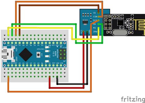
Connecting the NRF24L01 to a Microcontroller
To use the NRF24L01 module in your project, you need to connect it to a microcontroller. The following table shows the typical connections between the NRF24L01 and a generic microcontroller:
| NRF24L01 Pin | Microcontroller Pin |
|---|---|
| VCC | 3.3V |
| GND | GND |
| CE | GPIO |
| CSN | GPIO (SPI Chip Select) |
| SCK | SPI Clock |
| MOSI | SPI MOSI |
| MISO | SPI MISO |
| IRQ | GPIO (Optional) |
It is important to ensure that the microcontroller’s SPI peripheral is configured correctly to communicate with the NRF24L01. The SPI mode should be set to 0 (CPOL = 0, CPHA = 0), and the data order should be MSB first.

NRF24L01 Configuration and Operation
To use the NRF24L01 module effectively, you need to configure its various settings and operate it according to your application’s requirements. The module’s configuration is done by writing to its internal registers via the SPI interface. Some of the key configuration settings include:
- RF channel: The NRF24L01 supports 125 RF channels in the 2.4 GHz band. You can select the desired channel by writing to the RF_CH register.
- Data rate: The module supports three data rates: 250 kbps, 1 Mbps, and 2 Mbps. The data rate is configured using the RF_SETUP register.
- Output power: The NRF24L01 allows you to set the output power level using the RF_SETUP register. The available output power levels are -18 dBm, -12 dBm, -6 dBm, and 0 dBm.
- Address width: The module supports configurable address widths from 3 to 5 bytes. The address width is set using the SETUP_AW register.
- Automatic Packet Handling: The NRF24L01 features Enhanced ShockBurst™, which automatically handles packet assembly, timing, acknowledgments, and retransmissions. This feature is enabled by default and can be configured using various registers.
To transmit data, you need to follow these general steps:
- Set the module to TX mode by writing to the CONFIG register.
- Write the payload data to the TX FIFO using the W_TX_PAYLOAD command.
- Pull the CE pin high to start the transmission.
- Wait for the IRQ pin to go low, indicating that the transmission is complete.
To receive data, you need to follow these general steps:
- Set the module to RX mode by writing to the CONFIG register.
- Pull the CE pin high to start listening for incoming packets.
- Wait for the IRQ pin to go low, indicating that a packet has been received.
- Read the received payload data from the RX FIFO using the R_RX_PAYLOAD command.
For more detailed information on configuring and operating the NRF24L01, refer to the module’s datasheet and application notes provided by Nordic Semiconductor.

Example Projects Using the NRF24L01
Here are a few example projects that demonstrate the usage of the NRF24L01 module:
Wireless Temperature Sensor
In this project, an NRF24L01 module is connected to a temperature sensor (e.g., DS18B20) and a microcontroller (e.g., Arduino). The temperature data is periodically read from the sensor and transmitted wirelessly to a receiver unit, which displays the temperature on an LCD or sends it to a computer for logging.
Remote-Controlled Robot
This project uses two NRF24L01 modules: one connected to a microcontroller on a robot, and the other connected to a microcontroller on a remote control. The remote control sends commands wirelessly to the robot, which interprets the commands and controls the robot’s motors accordingly. The robot can send back status information or sensor data to the remote control for display or processing.
Wireless Sensor Network
In a wireless sensor network, multiple NRF24L01 modules are connected to various sensors (e.g., temperature, humidity, light) and deployed in different locations. The sensor nodes transmit their data wirelessly to a central hub or gateway, which collects and processes the data. The NRF24L01’s multi-channel capability allows for the creation of large-scale sensor networks with minimal interference between nodes.
Troubleshooting Common Issues
When working with the NRF24L01 module, you may encounter some common issues. Here are a few troubleshooting tips:
- No communication between modules:
- Check the wiring connections between the NRF24L01 and the microcontroller.
- Ensure that the SPI peripheral is configured correctly (mode 0, MSB first).
- Verify that the CSN and CE pins are controlled properly.
-
Make sure the modules are configured to use the same RF channel and address.
-
Poor signal quality or limited range:
- Check the power supply voltage and ensure it is stable and within the specified range.
- Make sure the antenna is properly connected (if using an external antenna).
- Increase the output power level if possible.
- Reduce the data rate to improve signal quality and range.
-
Consider using the NRF24L01+PA+LNA version for better performance.
-
Intermittent or sporadic communication:
- Ensure that the power supply is clean and free from noise.
- Add decoupling capacitors close to the VCC and GND pins of the module.
- Increase the retry count and delay between retries in the Enhanced ShockBurst™ settings.
- Implement error handling and data validation in your firmware.
If you encounter persistent issues, consult the NRF24L01 datasheet, application notes, and online resources for further guidance and support.
FAQ
- What is the maximum range of the NRF24L01 module?
-
The maximum range of the NRF24L01 module depends on various factors, such as the environment, output power level, and data rate. In ideal conditions (open space, maximum output power, and lowest data rate), the range can reach up to 100 meters. However, in practical applications, the range is typically shorter due to obstacles and interference.
-
Can I use the NRF24L01 module with a 5V microcontroller?
-
No, the NRF24L01 module is designed to operate with a power supply between 1.9V and 3.6V. Connecting it directly to a 5V microcontroller can damage the module. If you need to interface the NRF24L01 with a 5V system, you must use level shifters to convert the 5V signals to 3.3V.
-
How many NRF24L01 modules can communicate simultaneously?
-
The NRF24L01 supports 125 RF channels, allowing multiple modules to communicate simultaneously on different channels. However, the actual number of modules that can communicate simultaneously depends on the specific application, data rate, and network topology. In a star network, the practical limit is around 6 to 8 modules per channel, while in a mesh network, the number can be higher.
-
Is the NRF24L01 module compatible with other 2.4 GHz devices, such as Wi-Fi and Bluetooth?
-
The NRF24L01 operates in the 2.4 GHz ISM band, which is also used by Wi-Fi, Bluetooth, and other wireless technologies. While these devices can coexist in the same environment, there is a possibility of interference. To minimize interference, you can select RF channels that are not overlapping with the channels used by other devices in the area.
-
Can I use the NRF24L01 module for audio or video transmission?
- The NRF24L01 is primarily designed for low-data-rate applications, such as sensor data, control commands, and short messages. Its maximum data rate of 2 Mbps is not sufficient for high-quality audio or video transmission. For such applications, you should consider using other wireless modules or technologies specifically designed for multimedia streaming.
Conclusion
The NRF24L01 is a versatile and cost-effective wireless transceiver module that finds applications in various fields, from hobby projects to industrial systems. By understanding the NRF24L01 pinout, features, and configuration, you can successfully integrate this module into your projects and create reliable wireless communication systems.
Remember to follow best practices when designing your circuits, such as providing a clean power supply, using decoupling capacitors, and properly controlling the module’s pins. If you encounter any issues, refer to the troubleshooting tips and consult the module’s documentation and online resources for further assistance.
With its low power consumption, configurable parameters, and Enhanced ShockBurst™ technology, the NRF24L01 module offers a robust and efficient solution for wireless connectivity in a wide range of applications. By leveraging its capabilities and following the guidelines outlined in this comprehensive review, you can unlock the full potential of the NRF24L01 and create innovative wireless projects.
No responses yet