What are Blocking Oscillators?
A blocking oscillator is a type of electronic oscillator circuit that generates a periodic output signal using a single-stage amplifier and a positive feedback network consisting of a transformer or capacitor. The key characteristic of a blocking oscillator is that the active device, usually a transistor, is periodically cut off or “blocked” for a portion of each cycle, giving it a low duty cycle rectangular output waveform.
Blocking oscillators are simple, low-cost circuits that can generate narrow pulses at a wide range of frequencies. They are commonly used in applications such as:
- Pulse generation
- Timing circuits
- Frequency dividers
- Trigger circuits
- Switched-mode power supplies
How Do Blocking Oscillators Work?
The basic operating principle of a blocking oscillator relies on the switching of the active device between saturation and cutoff. This is achieved through positive feedback from the output back to the input, causing the circuit to alternately charge and discharge a timing capacitor.
Here is a step-by-step explanation of how a typical blocking oscillator operates:
-
When power is first applied, the transistor is off and not conducting. The timing capacitor begins charging through the base-emitter junction of the transistor.
-
Once the capacitor voltage reaches the turn-on threshold of the transistor, it begins conducting collector current. This induces a voltage in the feedback winding of the transformer which is applied back to the transistor base, driving it into saturation.
-
With the transistor saturated, the timing capacitor discharges rapidly through the transistor. The collector current reaches a peak then diminishes as the capacitor discharges.
-
The drop in collector current causes a corresponding drop in the feedback voltage applied to the base. This quickly drives the transistor into cutoff.
-
With the transistor off, the timing capacitor begins charging again and the cycle repeats.
The frequency of oscillation is primarily determined by the RC time constant of the timing capacitor and base resistor. The pulse width is governed by how long it takes the capacitor to discharge through the saturated transistor.
Some key waveforms in a blocking oscillator circuit:
| Waveform | Description |
|---|---|
| Base voltage | Exponential growth as capacitor charges, sharp spike from positive feedback, then cutoff |
| Collector voltage | Low during transistor on-time, then high-voltage spike as transistor cuts off |
| Collector current | Exponential decay as capacitor discharges, then cutoff |

Types of Blocking Oscillators
Blocking oscillators can be broadly categorized based on the type of active device used and the specific feedback network configuration. The two main types are:
Transistor Blocking Oscillator
The most common type of blocking oscillator uses a bipolar junction transistor (BJT) as the active device. The feedback network typically consists of a transformer with the base winding providing positive feedback to the transistor input.
A typical transistor blocking oscillator circuit looks like this:
The frequency of oscillation is approximately:
$f = \frac{1}{T} = \frac{1}{C(R_1 + R_2)\ln(\frac{V_{CC}}{V_{CC} – V_{BE}})}$
where:
– $f$ is the frequency in Hz
– $T$ is the period in seconds
– $C$ is the timing capacitor value in farads
– $R_1$ is the resistor from base to ground in ohms
– $R_2$ is the resistor from base to $V_{CC}$ in ohms
– $V_{CC}$ is the supply voltage in volts
– $V_{BE}$ is the base-emitter voltage drop of the transistor (typically 0.6-0.7V for silicon)
Transistor blocking oscillators are simple and reliable. They can generate frequencies from the low kHz range up to several MHz. The transformer provides DC isolation between input and output.
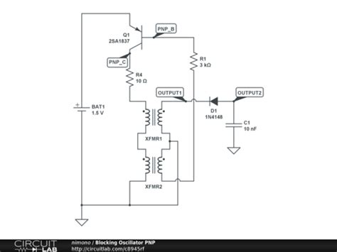
Diode or Capacitor Blocking Oscillator
An alternative blocking oscillator configuration uses a diode or capacitor for the feedback network instead of a transformer. This allows for an even simpler circuit, but lacks the DC isolation of a transformer.
A diode blocking oscillator looks like this:
The diode serves to clamp the capacitor voltage and provide a low-impedance discharge path. It allows for faster switching than a resistor alone.
A capacitor blocking oscillator replaces the base resistor divider with a capacitor:
The base capacitor $C_B$ blocks any DC feedback current, resulting in shorter output pulses. The frequency is controlled by the $R_BC_B$ time constant.
Diode and capacitor blocking oscillators are limited to lower power and frequency ranges than transformer-coupled versions, but their simplicity makes them useful for uncritical applications.

Applications of Blocking Oscillators
Blocking oscillators find use in a variety of electronic systems where a simple, low-cost source of narrow pulses or a low-duty cycle waveform is needed. Some common applications include:
Pulse Generation
One of the most basic uses for a blocking oscillator is as a rectangular pulse generator. The narrow output pulses can be used to trigger other circuits, drive displays, or provide a clock signal.
Pulse parameters like frequency, width, and amplitude can be adjusted by proper selection of the RC timing components. Very short pulses in the nanosecond range are possible.
Frequency Division
By counting a certain number of incoming pulses and generating one output pulse in response, a blocking oscillator can act as a frequency divider. Multiple blocking oscillator stages can be cascaded for higher division ratios.
For example, a 1 MHz blocking oscillator preceded by a divide-by-10 counter would generate 100 kHz output pulses. This technique is often used to derive lower-frequency clocks from a higher-frequency reference.
Switch-Mode Power Supplies
Many switching power supply topologies use a blocking oscillator to generate the switching control pulses. The narrow pulses minimize switching losses in the power devices.
Some examples of switching supplies that may incorporate a blocking oscillator:
- Flyback converter
- Forward converter
- Push-pull converter
- Ringing choke converter
In these applications, the blocking oscillator is typically synchronized to an external clock to regulate the output voltage or current.
TV Vertical Deflection
Blocking oscillators were once commonly used to generate the vertical deflection sawtooth waveform in CRT televisions and monitors. A synchronized burst of pulses from the blocking oscillator would rapidly discharge a capacitor, creating the vertical retrace interval.
Though largely obsolete now, this application was one of the primary drivers of blocking oscillator development in the early days of television.

Blocking Oscillator Design Considerations
When designing a blocking oscillator circuit for a particular application, several key factors must be considered:
Frequency and Duty Cycle
The desired operating frequency and duty cycle will dictate the choice of timing components $R$ and $C$. Higher frequencies will require smaller capacitor values and resistances.
Duty cycle (the ratio of pulse width to the full period) is typically very low in a blocking oscillator, often less than 10%. Shorter pulses yield lower duty cycles.
Output Pulse Shape
The shape of the output pulse is determined by the sort of load connected and the feedback network used. Resistive loads will give a more trapezoidal pulse shape, while inductive loads result in a sharper spike.
A transformer with a high turns ratio will give narrower pulses with faster rise and fall times. Diode or capacitor feedback will also result in shorter pulses compared to a resistor.
Transistor Selection
The choice of transistor depends on the power handling capability and switching speed needed. Higher frequency operation requires a transistor with a high $f_T$ (transition frequency).
Power dissipation, especially under fault conditions, must also be considered. The transistor will see high peak currents during discharge. Sufficient base drive must be provided to ensure saturation.
Transformer Design
If a transformer-coupled design is used, the transformer specifications are critical to proper circuit operation. Key parameters include:
- Turns ratio (primary to feedback)
- Inductance
- Saturation current
- Leakage inductance
- Winding capacitance
The transformer core material must be chosen based on the desired frequency range and pulse shape. Ferrite cores are popular for their low losses at high frequencies.
Triggering and Synchronization
Some blocking oscillator designs incorporate a trigger input to allow external control of the output pulses. A trigger pulse applied to the base of the transistor can initiate an output pulse on demand.
For applications requiring synchronization to an external clock, a Phase-Locked Loop (PLL) can be used to control the blocking oscillator frequency. The PLL compares the oscillator output to the reference clock and adjusts the timing components accordingly.
Advantages and Disadvantages
Blocking oscillators have several key advantages:
- Simple, low-cost design
- Reliable operation
- Easily customized frequency and pulse width
- Wide frequency range (up to tens of MHz)
- Narrow output pulses with fast rise times
- Good noise immunity due to switching action
However, they also have some notable drawbacks:
- Poor frequency stability with changes in supply voltage or temperature
- High-amplitude spikes can cause EMI issues
- Limited output power
- Low duty cycle (not suitable for applications needing square waves)
- Transformer versions are bulky compared to other oscillator types
In general, blocking oscillators are best suited for applications where simplicity, low cost, and fast pulses are the main requirements, and frequency accuracy is less critical.
Troubleshooting Tips
If a blocking oscillator circuit is not functioning properly, here are some common issues to check:
- Verify the power supply voltage is correct and free of noise or ripple.
- Check the orientation and wiring of the transformer windings.
- Make sure the transistor is properly biased and not damaged. Measure $V_{BE}$ and $V_{CE}$ to verify.
- Check the value and polarity of the timing capacitor. An open or the wrong value can prevent oscillation.
- Look for cold solder joints or broken connections, especially in high-current paths.
- Confirm the load impedance is not too low. This can overdamp the oscillations.
An oscilloscope is an invaluable tool for diagnosing blocking oscillator faults. Observe the waveforms at the base and collector of the transistor and compare to expected behavior.
Frequently Asked Questions
What is the main difference between a blocking oscillator and other types like LC or RC oscillators?
The key distinguishing feature of a blocking oscillator is the use of a cutoff or “blocked” state in the active device to generate a narrow pulse output. Other oscillator types typically aim for a sinusoidal or square wave output with a 50% duty cycle.
Can a blocking oscillator be used as a sine wave generator?
No, the nature of a blocking oscillator’s operation results in a low-duty cycle rectangular wave output. It is not suitable for generating sinewaves. For that, an LC or Crystal Oscillator would be more appropriate.
What limits the maximum frequency of a blocking oscillator?
The upper frequency limit is set by the switching speed of the active device and the minimum achievable $RC$ time constant of the timing network. Transistor performance factors like transition frequency $f_T$ and switching losses come into play. Parasitic capacitances and inductances in the circuit wiring and transformer also become limiting factors at very high frequencies.
How can I change the output frequency of a blocking oscillator?
The two main ways to adjust the frequency are changing the timing capacitor value or the base resistor values. A smaller capacitance or resistance will increase the frequency and vice versa. The frequency can also be adjusted by applying an external control voltage to modify the transistor bias. For a wide tuning range, a variable capacitor like a varactor diode can be used.
What happens if the transistor is not driven into saturation?
If the transistor is not fully saturated, it will not be able to fully discharge the timing capacitor during the pulse interval. This will result in a higher output voltage level during the “low” state and will also limit the maximum collector current. The output pulses will be wider and more trapezoidal in shape. Circuit efficiency will be reduced due to higher switching losses in the linear region.
Conclusion
Blocking oscillators are a simple yet versatile circuit building block with a long history of use in electronic systems. Their ability to generate fast, narrow pulses with minimal components makes them well-suited for a range of pulse generation, timing, and power conversion applications.
While largely supplanted by more sophisticated designs in modern high-speed systems, blocking oscillators remain a valuable tool in the designer’s toolkit for lower-frequency, low-cost applications. A solid understanding of their operation and design principles is beneficial for anyone working with pulsed electronic circuits.
No responses yet