What is a Breadboard?
A breadboard is a rectangular plastic board with a grid of holes used for prototyping electronic circuits. It allows you to quickly and easily connect components without the need for soldering. Breadboards are an essential tool for anyone learning electronics or working on temporary circuit designs.
Anatomy of a Breadboard
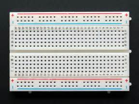
A typical breadboard consists of the following parts:
- Terminal strips: Two vertical columns of holes, usually labeled as “+” and “-“, used for connecting power supply and ground.
- Distribution strips: Horizontal rows of holes, divided into two sections by a central gap. Each row is connected internally, allowing components to be connected across the breadboard.
- DIP support: A gap in the center of the breadboard designed to accommodate Dual In-line Package (DIP) integrated circuits (ICs).
| Part | Description |
|---|---|
| Terminal strips | Vertical columns of holes for connecting power supply and ground |
| Distribution strips | Horizontal rows of holes divided by a central gap, used for connecting components |
| DIP support | A gap in the center of the breadboard for accommodating Dual In-line Package (DIP) integrated circuits |
How to Make Breadboard Connections
Step 1: Understanding the Breadboard Layout
Before making connections, it’s essential to understand the internal layout of a breadboard. The distribution strips are connected horizontally, while the terminal strips are connected vertically. The gap in the center of the breadboard separates the two halves of the distribution strips.
Step 2: Connecting Power and Ground
Begin by connecting the power supply and ground to the terminal strips. Typically, the red terminal strip is used for the positive voltage (VCC) and the blue or black terminal strip is used for ground (GND). Use jumper wires to connect the power supply to the appropriate terminal strips.
Step 3: Inserting Components
Insert the components into the breadboard, ensuring that their leads are properly aligned with the holes. Most components, such as resistors and capacitors, can be inserted directly into the distribution strips. DIP ICs should be placed across the central gap, with each pin inserted into a separate hole.
Step 4: Making Connections
Use jumper wires to connect the components according to your circuit diagram. When making connections, ensure that the jumper wires are inserted securely into the breadboard holes. Always double-check your connections to avoid shorts or incorrect connections.

Tips for Working with Breadboards
- Keep your workspace organized: Use color-coded jumper wires to make your connections more visually appealing and easier to follow.
- Use shorter jumper wires: Shorter jumper wires help keep your circuit neat and reduce the risk of accidentally pulling out connections.
- Double-check your connections: Before powering on your circuit, always double-check your connections to ensure they are correct and secure.
- Avoid overloading the breadboard: Be mindful of the current limitations of your breadboard and avoid overloading it with too many components or high-current devices.
- Use a multimeter: A multimeter can be a valuable tool for troubleshooting and verifying connections on your breadboard.

Common Breadboard Connection Mistakes
- Incorrect power and ground connections: Ensure that you have connected the power supply and ground to the correct terminal strips and that the polarity is correct.
- Loose or improper connections: Make sure that all jumper wires and component leads are securely inserted into the breadboard holes to avoid intermittent connections or shorts.
- Incorrect component orientation: Pay attention to the orientation of polarized components, such as electrolytic capacitors and diodes, to ensure they are inserted correctly.
- Accidentally connecting to the wrong row or column: Double-check your connections to ensure that you have connected the components to the intended rows and columns on the breadboard.
- Overloading the breadboard: Be aware of the current limitations of your breadboard and avoid overloading it with too many components or high-current devices.

Advanced Breadboard Techniques
Using Multiple Breadboards
For larger projects, you may need to use multiple breadboards. To connect breadboards together, use longer jumper wires to bridge the gaps between the distribution strips of adjacent breadboards. Ensure that the power and ground connections are maintained across all the breadboards.
Implementing Power Rails
Power rails are dedicated rows on the breadboard used for distributing power and ground to multiple components. By connecting the power supply and ground to the power rails, you can easily provide power to components across the breadboard without the need for individual connections.
Using Breadboard-CompatiBLE Modules
Many electronic modules, such as sensors and breakout boards, are designed to be breadboard-compatible. These modules have pins that can be directly inserted into the breadboard, making it easier to integrate them into your projects without the need for additional wiring.
Frequently Asked Questions (FAQ)
-
What is the purpose of the gap in the center of the breadboard?
The gap in the center of the breadboard is designed to accommodate DIP ICs. It allows the IC to be placed across the gap, with each pin inserted into a separate hole on either side of the breadboard. -
Can I reuse a breadboard after a project?
Yes, breadboards are reusable. After completing a project, you can remove the components and jumper wires, and the breadboard will be ready for your next project. However, over time, the contacts in the breadboard may wear out, reducing its reliability. -
How do I know which hole to insert a component into?
Refer to your circuit diagram and the breadboard layout to determine where each component should be inserted. Pay attention to the orientation of polarized components and ensure that the component leads are inserted into the correct rows and columns. -
Can I use a breadboard for high-voltage or high-current projects?
Breadboards are designed for low-voltage and low-current applications. They are not suitable for high-voltage or high-current projects, as they may not have the necessary insulation or current-carrying capacity. Always use appropriate tools and techniques when working with high-voltage or high-current circuits. -
What should I do if my circuit is not working on the breadboard?
If your circuit is not working as expected on the breadboard, follow these troubleshooting steps: - Double-check your connections and ensure that all jumper wires and component leads are securely inserted into the breadboard.
- Verify that your power supply and ground connections are correct and that the polarity is correct.
- Check the orientation of polarized components, such as electrolytic capacitors and diodes.
- Use a multimeter to test for continuity and verify that there are no shorts or open connections.
- Refer to your circuit diagram and compare it with your breadboard connections to identify any discrepancies.
Conclusion
Breadboards are an essential tool for prototyping and learning electronics. By understanding the anatomy of a breadboard and following the steps for making connections, you can quickly and easily build and test electronic circuits. Remember to keep your workspace organized, use proper techniques, and double-check your connections to ensure your projects work as intended. With practice and experience, you’ll become proficient in using breadboards and creating complex electronic projects.
No responses yet