What are Resistor Color Codes?
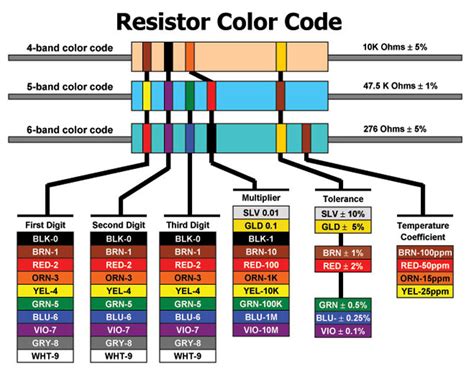
Resistor color codes are a standardized system used to identify the resistance value and tolerance of a resistor. The system consists of colored bands printed on the body of the resistor, with each color representing a specific number or multiplier. By reading these color codes, you can determine the resistance value of the resistor without the need for specialized measuring equipment.
History of Resistor Color Codes
The resistor color code system was developed in the 1920s by the Radio Manufacturers Association (RMA), now known as the Electronic Industries Alliance (EIA). The goal was to create a standardized method for identifying resistor values that could be easily interpreted by technicians and engineers.
Initially, the color code system used only three bands to represent the resistance value. However, as the need for more precise resistor values grew, a fourth band was added to indicate the tolerance of the resistor. In the 1970s, a fifth band was introduced to represent the temperature coefficient of the resistor.
How to Read Resistor Color Codes
Reading resistor color codes is a straightforward process once you understand the meaning of each color and its position on the resistor body. The standard color code consists of four or five colored bands, each representing a specific value or multiplier.
Four-Band Resistor Color Code
The four-band resistor color code is the most common and consists of the following bands:
- First band (left): First digit of the resistance value
- Second band: Second digit of the resistance value
- Third band: Multiplier
- Fourth band (right): Tolerance
| Color | Digit | Multiplier | Tolerance |
|---|---|---|---|
| Black | 0 | 1 | – |
| Brown | 1 | 10 | ±1% |
| Red | 2 | 100 | ±2% |
| Orange | 3 | 1,000 | – |
| Yellow | 4 | 10,000 | – |
| Green | 5 | 100,000 | ±0.5% |
| Blue | 6 | 1,000,000 | ±0.25% |
| Violet | 7 | 10,000,000 | ±0.1% |
| Gray | 8 | 100,000,000 | ±0.05% |
| White | 9 | 1,000,000,000 | – |
| Gold | – | 0.1 | ±5% |
| Silver | – | 0.01 | ±10% |
To read a four-band resistor, follow these steps:
- Read the first two bands from left to right to determine the first two digits of the resistance value.
- The third band represents the multiplier, which indicates the number of zeros to be added after the first two digits.
- The fourth band represents the tolerance of the resistor, which is the acceptable deviation from the nominal resistance value.
For example, if a resistor has the color code: Yellow, Violet, Orange, Gold, the resistance value would be:
- First digit: Yellow (4)
- Second digit: Violet (7)
- Multiplier: Orange (1,000)
- Tolerance: Gold (±5%)
Therefore, the resistance value is 47 × 1,000 = 47,000 ohms or 47 kΩ, with a tolerance of ±5%.
Five-Band Resistor Color Code
The five-band resistor color code is similar to the four-band code but includes an additional band to represent the temperature coefficient of the resistor. The temperature coefficient indicates how much the resistance value changes with temperature variations.
The five-band color code consists of the following bands:
- First band (left): First digit of the resistance value
- Second band: Second digit of the resistance value
- Third band: Third digit of the resistance value
- Fourth band: Multiplier
- Fifth band (right): Tolerance
The color codes for the first four bands are the same as in the four-band system. The fifth band represents the tolerance and uses the same colors as the four-band system, with the addition of the following:
| Color | Tolerance |
|---|---|
| Brown | ±1% |
| Red | ±2% |
| Green | ±0.5% |
| Blue | ±0.25% |
| Violet | ±0.1% |
| Gray | ±0.05% |
| Gold | ±5% |
| Silver | ±10% |
To read a five-band resistor, follow these steps:
- Read the first three bands from left to right to determine the first three digits of the resistance value.
- The fourth band represents the multiplier, which indicates the number of zeros to be added after the first three digits.
- The fifth band represents the tolerance of the resistor.
For example, if a resistor has the color code: Red, Yellow, Black, Orange, Brown, the resistance value would be:
- First digit: Red (2)
- Second digit: Yellow (4)
- Third digit: Black (0)
- Multiplier: Orange (1,000)
- Tolerance: Brown (±1%)
Therefore, the resistance value is 240 × 1,000 = 240,000 ohms or 240 kΩ, with a tolerance of ±1%.

Importance of Resistor Color Codes in Electronic Circuits
Resistor color codes play a crucial role in electronic circuit design and troubleshooting. By accurately identifying the resistance value and tolerance of a resistor, engineers and technicians can ensure that the circuit functions as intended and meets the required specifications.
Proper Component Selection
When designing an electronic circuit, it is essential to select the appropriate resistor values to achieve the desired voltage drops, current limiting, and signal conditioning. Resistor color codes enable designers to quickly identify the resistance values of available resistors and choose the most suitable components for their circuits.
Troubleshooting and Repair
In the event of a circuit malfunction, technicians often need to check the resistance values of individual components to identify potential issues. Resistor color codes allow technicians to determine the expected resistance value of a resistor without the need for specialized measuring equipment, making the troubleshooting process more efficient.
Standardization and Compatibility
The standardized resistor color code system ensures that resistors manufactured by different companies are easily identifiable and interchangeable. This compatibility simplifies the procurement process and allows for the use of resistors from various sources in the same circuit without causing confusion or errors.

Frequently Asked Questions (FAQ)
-
Q: What is the difference between four-band and five-band resistor color codes?
A: The main difference between four-band and five-band resistor color codes is the presence of an additional band in the five-band system. The extra band represents the third digit of the resistance value, allowing for more precise resistance values. The four-band system is more common and typically sufficient for most applications. -
Q: How do I determine the tolerance of a resistor using the color code?
A: The tolerance of a resistor is indicated by the last band in the color code (the fourth band in a four-band system or the fifth band in a five-band system). Each color represents a specific tolerance value, such as brown for ±1%, red for ±2%, gold for ±5%, and silver for ±10%. -
Q: Can I use a resistor with a higher tolerance than specified in the circuit design?
A: Yes, you can use a resistor with a higher tolerance than specified in the circuit design. However, using a resistor with a lower tolerance than required may cause the circuit to perform outside its intended specifications. It is generally recommended to use resistors with the specified tolerance or better to ensure optimal circuit performance. -
Q: What should I do if I encounter a resistor with no visible color code?
A: If you encounter a resistor with no visible color code, you can use a multimeter to measure its resistance value directly. Set the multimeter to the appropriate resistance range and connect the probes to the resistor leads. The multimeter will display the resistance value in ohms (Ω). Keep in mind that the measured value may vary slightly from the nominal value due to the resistor’s tolerance. -
Q: Are there any other marking systems for resistors besides color codes?
A: Yes, there are alternative marking systems for resistors, such as numerical codes and SMD (Surface Mount Device) codes. Numerical codes use a combination of numbers and letters to indicate the resistance value and tolerance, while SMD codes use a alphanumeric system to represent the resistance value in a compact format suitable for small surface-mount resistors. However, the color code system remains the most widely used and recognized method for identifying through-hole resistors.

Conclusion
Resistor color codes are a vital aspect of electronic circuit design and maintenance. By providing a standardized system for identifying resistance values and tolerances, color codes enable engineers and technicians to quickly and accurately select the appropriate components for their circuits. Understanding how to read resistor color codes is an essential skill for anyone working with electronic circuits, as it simplifies the design, troubleshooting, and repair processes.
As technology advances and electronic devices become increasingly complex, the importance of resistor color codes remains unchanged. By mastering the color code system, you can confidently navigate the world of electronic components and contribute to the development of innovative and reliable electronic systems.
No responses yet