Introduction to Voltage Doubler Circuits
A voltage doubler is an electronic circuit that converts an alternating current (AC) input voltage to a direct current (DC) output voltage that is twice the peak value of the input voltage. This simple yet effective circuit finds applications in various fields, such as power supplies, electronic devices, and high-voltage systems. The voltage doubler circuit offers a cheaper and lighter alternative to traditional transformer-Rectifier Circuits, making it an attractive option for many applications.
Advantages of Voltage Doubler Circuits
- Cost-effective: Voltage doubler circuits require fewer components compared to transformer-rectifier circuits, making them a more economical solution.
- Lightweight: The absence of a bulky transformer in voltage doubler circuits significantly reduces the overall weight of the system.
- Compact: Voltage doubler circuits occupy less space due to their simpler design and fewer components.
- Efficiency: Voltage doubler circuits can achieve high efficiency, especially when dealing with low-power applications.
How Voltage Doubler Circuits Work
A basic voltage doubler circuit consists of two capacitors and two diodes connected in a specific configuration. The circuit operates in two stages: the charging stage and the discharging stage.
Charging Stage
During the positive half-cycle of the AC input voltage, the first capacitor (C1) charges through the first diode (D1) to the peak value of the input voltage. The second diode (D2) is reverse-biased during this stage, preventing current flow through the second capacitor (C2).
Discharging Stage
During the negative half-cycle of the AC input voltage, the first diode (D1) becomes reverse-biased, isolating the first capacitor (C1) from the input. The second diode (D2) becomes forward-biased, allowing the second capacitor (C2) to charge to the peak value of the input voltage plus the voltage stored in the first capacitor (C1). This results in a DC output voltage that is approximately twice the peak value of the AC input voltage.
The following table summarizes the voltage across each component during the charging and discharging stages:
| Component | Charging Stage | Discharging Stage |
|---|---|---|
| C1 | Vpeak | Vpeak |
| C2 | 0 | 2Vpeak |
| D1 | Forward-biased | Reverse-biased |
| D2 | Reverse-biased | Forward-biased |

Types of Voltage Doubler Circuits
There are several types of voltage doubler circuits, each with its own characteristics and applications.
Half-Wave Voltage Doubler
The half-wave voltage doubler is the simplest and most basic type of voltage doubler circuit. It consists of two capacitors and two diodes connected in the configuration described earlier. The half-wave voltage doubler is suitable for low-power applications and is often used in electronic devices such as LED drivers and backlight inverters.
Full-Wave Voltage Doubler
The full-wave voltage doubler, also known as the bridge voltage doubler, uses four diodes instead of two. This configuration allows the circuit to rectify both the positive and negative half-cycles of the AC input voltage, resulting in a smoother DC output voltage with less ripple. Full-wave voltage doublers are commonly used in power supplies and high-voltage applications.
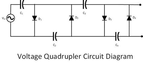
Cascaded Voltage Doubler
Cascaded voltage doubler circuits consist of multiple stages of voltage doubler circuits connected in series. Each stage doubles the voltage of the previous stage, allowing the circuit to achieve higher output voltages. Cascaded voltage doublers are used in applications that require very high DC voltages, such as X-ray machines, particle accelerators, and laser systems.

Applications of Voltage Doubler Circuits
Voltage doubler circuits find applications in various fields, ranging from consumer electronics to industrial systems. Some common applications include:
-
Power supplies: Voltage doubler circuits are used in power supplies to generate high DC voltages from low AC input voltages. They are particularly useful in portable devices and battery-powered systems.
-
Electronic devices: Many electronic devices, such as LCD backlight inverters, LED drivers, and electronic flash units, employ voltage doubler circuits to generate the required high voltages from low-voltage batteries.
-
High-voltage systems: Cascaded voltage doubler circuits are used in high-voltage systems, such as X-ray machines, particle accelerators, and laser systems, to generate the extremely high voltages needed for their operation.
-
Automotive electronics: Voltage doubler circuits are used in automotive electronics to generate high voltages for various applications, such as ignition systems, headlight drivers, and fuel injectors.

Designing Voltage Doubler Circuits
When designing a voltage doubler circuit, several factors must be considered to ensure optimal performance and reliability.
Component Selection
The selection of capacitors and diodes is crucial in voltage doubler circuits. The capacitors should have a voltage rating higher than the expected output voltage and should be chosen based on the required capacitance value and the operating frequency of the circuit. The diodes should have a sufficient current rating and a low forward voltage drop to minimize power losses.
Ripple and Regulation
The output voltage of a voltage doubler circuit will have some ripple, which is the residual AC component superimposed on the DC output voltage. The amount of ripple depends on the capacitance of the capacitors and the load current. To reduce the ripple, larger capacitance values can be used, or additional filtering stages can be added to the circuit.
Voltage regulation is another important factor to consider when designing voltage doubler circuits. The output voltage of a voltage doubler circuit will vary with changes in the load current and the input voltage. To maintain a stable output voltage, voltage regulation techniques such as feedback control or voltage stabilization can be employed.
Power Losses and Efficiency
Power losses in voltage doubler circuits occur mainly due to the forward voltage drop of the diodes and the equivalent series resistance (ESR) of the capacitors. To minimize power losses and improve efficiency, diodes with low forward voltage drop and capacitors with low ESR should be selected. Additionally, the circuit should be designed to operate at the optimal frequency to minimize switching losses.
Frequently Asked Questions (FAQ)
- What is the main advantage of using a voltage doubler circuit over a transformer-rectifier circuit?
The main advantages of using a voltage doubler circuit over a transformer-rectifier circuit are its lower cost, lighter weight, and more compact size. Voltage doubler circuits require fewer components and do not need a bulky transformer, making them a more economical and space-saving solution.
- Can a voltage doubler circuit be used to generate very high voltages?
Yes, by cascading multiple stages of voltage doubler circuits in series, it is possible to generate very high voltages. Cascaded voltage doubler circuits are used in applications that require extremely high DC voltages, such as X-ray machines, particle accelerators, and laser systems.
- What factors should be considered when selecting components for a voltage doubler circuit?
When selecting components for a voltage doubler circuit, the voltage rating, capacitance value, and operating frequency should be considered for capacitors. For diodes, the current rating and forward voltage drop are important factors. Components with higher voltage ratings, lower forward voltage drop, and low equivalent series resistance (ESR) are preferred to minimize power losses and improve efficiency.
- How can the ripple in the output voltage of a voltage doubler circuit be reduced?
The ripple in the output voltage of a voltage doubler circuit can be reduced by using larger capacitance values for the capacitors or by adding additional filtering stages to the circuit. Increasing the capacitance will help smooth out the ripple, while additional filtering stages can further attenuate the AC component of the output voltage.
- Are voltage doubler circuits suitable for high-power applications?
Voltage doubler circuits are generally more suitable for low-power applications due to the limitations imposed by the components’ current handling capabilities and power dissipation. For high-power applications, transformer-rectifier circuits or other specialized power conversion techniques are typically used to ensure efficient and reliable operation.
Conclusion
Voltage doubler circuits offer a cost-effective, lightweight, and compact alternative to traditional transformer-rectifier circuits for generating high DC voltages from low AC input voltages. By understanding the working principle, types, and design considerations of voltage doubler circuits, engineers and technicians can effectively implement these circuits in various applications, such as power supplies, electronic devices, and high-voltage systems.
As with any electronic circuit design, careful component selection, consideration of ripple and regulation, and optimization of power losses and efficiency are essential for achieving the desired performance and reliability. With the proper design and implementation, voltage doubler circuits can provide an efficient and economical solution for a wide range of applications requiring high DC voltages.
No responses yet