Key Features of the LM350
The LM350 offers several key features that make it an attractive choice for voltage regulation:
- Adjustable output voltage from 1.2V to 33V
- Output current capability in excess of 3A
- Excellent line and load regulation
- Internal current limiting and thermal overload protection
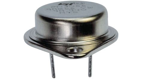
- Available in TO-220, TO-263, and TO-3 packages
Specifications
| Parameter | Value |
|---|---|
| Input Voltage Range | 3V to 35V |
| Output Voltage Range | 1.2V to 33V |
| Output Current | >3A |
| Line Regulation | 0.01%/V |
| Load Regulation | 0.1% |
| Ripple Rejection | 75 dB |
| Current Limit | 3.5A |
| Thermal Overload Protection | Yes |

Basic LM350 Voltage Regulator Circuit
The most basic LM350 voltage regulator circuit consists of the LM350 IC, two resistors (R1 and R2), and input/output capacitors (Cin and Cout). The output voltage is set by the ratio of R1 and R2 according to the following equation:
Vout = 1.25V * (1 + R2 / R1)
Here’s a schematic of the basic LM350 voltage regulator circuit:
[Insert schematic image]
To calculate the resistor values for a desired output voltage:
- Choose a value for R1 (typically between 100Ω and 1kΩ)
- Calculate R2 using the equation: R2 = R1 * (Vout / 1.25V – 1)
For example, to set the output voltage to 5V with R1 = 220Ω:
R2 = 220Ω * (5V / 1.25V – 1) = 660Ω

Adjustable Voltage Regulator with Potentiometer
You can make the LM350 output voltage adjustable by replacing the fixed resistor R2 with a potentiometer. This allows you to vary the output voltage within the LM350’s range by adjusting the potentiometer.
[Insert schematic image]
The output voltage range will depend on the value of R1 and the potentiometer’s resistance. For example, with R1 = 220Ω and a 5kΩ potentiometer, the output voltage can be adjusted from about 1.3V to 28V.

Current Boosting with the LM350
While the LM350 can provide over 3A of output current, you can increase its current capability even further by adding a power transistor. This technique, known as current boosting, allows the LM350 to regulate voltage while the transistor handles the bulk of the load current.
[Insert schematic image]
In this configuration, the LM350 controls the base of the power transistor, which in turn supplies current to the load. The current-boosting transistor must be chosen based on the expected load current and power dissipation.
LM350 as a Constant Current Source
The LM350 can also be configured as a constant current source, which is useful for charging batteries, driving LEDs, and other current-regulated applications. In this configuration, the LM350’s output voltage is set by the voltage across a current-sensing resistor (Rs).
[Insert schematic image]
The constant current value is determined by the equation:
Iout = 1.25V / Rs
For example, to set a constant current of 1A, use a 1.25Ω resistor for Rs.
Protecting the LM350 from Input Transients
In applications where the input voltage may be subject to transient spikes, it’s important to protect the LM350 from damage. One way to do this is by adding a transient voltage suppressor (TVS) diode across the input.
[Insert schematic image]
The TVS diode clamps any voltage spikes that exceed its breakdown voltage, preventing them from reaching the LM350. Choose a TVS diode with a breakdown voltage slightly higher than the maximum expected input voltage.
Troubleshooting LM350 Circuits
If your LM350 voltage regulator circuit isn’t working as expected, here are some troubleshooting tips:
- Check the input voltage: Ensure the input voltage is within the LM350’s specified range (3V to 35V).
- Verify the output voltage: Measure the output voltage and compare it to the expected value based on your resistor calculations.
- Check for short circuits: Look for any unintended short circuits across the input, output, or adjustment pins.
- Inspect solder joints: Poor solder joints can cause intermittent connections or high resistance.
- Confirm component values: Double-check that you’re using the correct resistor and capacitor values.
- Monitor temperature: If the LM350 is overheating, it may indicate a problem with the circuit or an excessive load current.
Applications
The LM350’s adjustable voltage and high current capability make it suitable for a wide range of applications, including:
- Power supplies for electronic devices
- Battery Chargers
- LED drivers
- Motor speed controls
- Solar panel voltage regulation
- Automotive electronics
FAQ
-
Q: Can I use the LM350 with input voltages higher than 35V?
A: No, the LM350’s maximum input voltage is 35V. Exceeding this limit may damage the device. -
Q: What’s the difference between the LM350 and the LM317?
A: The LM350 is a higher-current version of the LM317, capable of providing over 3A of output current compared to the LM317’s 1.5A. -
Q: Do I need to use heat sinks with the LM350?
A: It depends on the load current and power dissipation. If the LM350 is expected to dissipate more than a few watts, a heat sink is recommended to prevent thermal overload. -
Q: Can I parallel multiple LM350s for even higher current output?
A: Yes, you can parallel LM350s to increase the total output current. However, ensure that each LM350 has its own current-limiting resistor to balance the load. -
Q: What happens if the output is short-circuited?
A: The LM350 has built-in current limiting and thermal overload protection. In case of a short circuit, the current will be limited to a safe value, and the device will shut down if it overheats.
Conclusion
The LM350 is a powerful and versatile adjustable voltage regulator that finds use in a wide array of applications. By understanding its features, specifications, and various circuit configurations, you can effectively utilize the LM350 in your projects. Always remember to consider factors such as input voltage range, output current requirements, and power dissipation when designing your LM350-based voltage regulator circuits.
No responses yet