Introduction to ULN2003 IC
The ULN2003 is a high-voltage, high-current Darlington transistor array IC commonly used for driving inductive loads such as relays, solenoids, DC motors, and stepper motors. This versatile integrated circuit features seven open-collector Darlington pairs with common emitters, capable of switching loads up to 500 mA and 50 V per channel. The ULN2003’s robust design and built-in suppression diodes make it an ideal choice for a wide range of applications, from automotive systems to industrial control and home automation projects.
In this comprehensive guide, we will dive deep into the ULN2003 Pinout, its functional diagram, and key features. We will also explore practical applications, provide example circuits, and answer frequently asked questions to help you effectively integrate this powerful IC into your projects.
ULN2003 Pinout and Pin Description
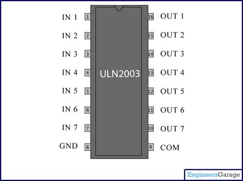
The ULN2003 is available in several package types, including DIP (Dual Inline Package), SOP (Small Outline Package), and SMD (Surface Mount Device). The most common package is the 16-pin DIP. Let’s take a closer look at the ULN2003 pinout and the function of each pin.
| Pin Number | Pin Name | Description |
|---|---|---|
| 1 | 1B | Input 1 |
| 2 | 1C | Output 1 |
| 3 | 2B | Input 2 |
| 4 | 2C | Output 2 |
| 5 | 3B | Input 3 |
| 6 | 3C | Output 3 |
| 7 | 4B | Input 4 |
| 8 | GND | Ground |
| 9 | COM | Common Collector Supply Voltage |
| 10 | 5C | Output 5 |
| 11 | 5B | Input 5 |
| 12 | 6C | Output 6 |
| 13 | 6B | Input 6 |
| 14 | 7C | Output 7 |
| 15 | 7B | Input 7 |
| 16 | 4C | Output 4 |
As shown in the table above, the ULN2003 has seven input pins (1B to 7B) and seven corresponding output pins (1C to 7C). Each input pin is connected to the base of a Darlington transistor pair, while the output pins are the collectors of the Darlington pairs. The emitters of all Darlington pairs are connected to the common emitter pin (COM), which is typically tied to ground.
The COM pin (pin 9) is the common collector supply voltage pin. This pin should be connected to the positive supply voltage, which can range from 5V to 50V, depending on the application and the load being driven.
The GND pin (pin 8) is the ground connection for the IC. It is essential to provide a proper ground connection to ensure stable operation and to avoid damage to the device.

ULN2003 Functional Diagram
To better understand how the ULN2003 works, let’s examine its functional diagram.
[Insert functional diagram image here]
As depicted in the functional diagram, each channel of the ULN2003 consists of a Darlington transistor pair with a common emitter. The input signal is applied to the base of the first transistor (Q1), which controls the second transistor (Q2) in the Darlington configuration. When a high input signal is applied to the base of Q1, both transistors turn on, allowing current to flow from the collector (output) to the emitter (COM).
The ULN2003 also features built-in suppression diodes connected between each output and the COM pin. These diodes help protect the IC from voltage spikes generated by inductive loads when they are switched off. The suppression diodes clamp the induced voltage to a safe level, preventing damage to the Darlington transistors and other sensitive components in the circuit.

Key Features and Specifications
The ULN2003 offers several key features that make it a popular choice for driving inductive loads:
- High voltage and current capability: Each channel can switch loads up to 500 mA and withstand voltages up to 50 V.
- Built-in suppression diodes: Integrated suppression diodes protect the IC and other components from voltage spikes generated by inductive loads.
- Darlington transistor configuration: The Darlington pair provides high current gain, allowing the IC to be driven by low-current control signals.
- Open-collector outputs: The open-collector design allows for flexibility in connecting multiple outputs or interfacing with other devices.
- Wide operating voltage range: The ULN2003 can operate with supply voltages ranging from 5 V to 50 V.
- Compact packaging: Available in various package types, including DIP, SOP, and SMD, for easy integration into different projects.
Here are some important specifications for the ULN2003:
| Parameter | Value |
|---|---|
| Maximum output voltage | 50 V |
| Maximum output current | 500 mA |
| Peak output current | 600 mA |
| Input voltage range | 2.7 V to 7 V |
| Input current (per channel) | 1.35 mA |
| Switching time (ON) | 0.25 μs (typ.) |
| Switching time (OFF) | 0.65 μs (typ.) |
| Operating temperature range | -40°C to 85°C |

Applications of ULN2003
The ULN2003 is widely used in various applications that require driving inductive loads or high-current devices. Some common applications include:
-
Stepper motor control: The ULN2003 is often used in conjunction with stepper motor driver boards to control the stepping sequence and direction of stepper motors.
-
Relay driving: The high voltage and current capabilities of the ULN2003 make it suitable for driving relays in industrial control systems, home automation, and other applications.
-
Solenoid control: The ULN2003 can be used to control solenoids in various applications, such as valve control, door locks, and vending machines.
-
LED display drivers: The open-collector outputs of the ULN2003 can be used to drive LED displays, allowing for multiplexed control of multiple segments or rows.
-
Automotive systems: The ULN2003 is used in automotive applications for driving loads such as fuel injectors, ignition coils, and other high-current devices.
Example Circuits
Let’s explore a few example circuits that demonstrate how to use the ULN2003 in practical applications.
Stepper Motor Control
In this example, we will use a ULN2003 to control a unipolar stepper motor. The circuit diagram below shows the connections between the ULN2003, a microcontroller (such as an Arduino), and the stepper motor.
[Insert stepper motor control circuit diagram here]
The microcontroller generates the stepping sequence by sending the appropriate control signals to the inputs of the ULN2003 (pins 1B to 4B). The ULN2003 then switches the motor windings on and off according to the input signals, allowing the stepper motor to rotate in the desired direction and with the specified step size.
Relay Driving
The following circuit demonstrates how to use a ULN2003 to drive a relay. The relay can be used to switch high-voltage or high-current loads, such as lights, motors, or other devices.
[Insert relay driving circuit diagram here]
In this example, the input signal is applied to one of the ULN2003’s input pins (e.g., 1B). When the input is high, the corresponding Darlington transistor pair turns on, allowing current to flow through the relay coil. This energizes the relay, causing its contacts to switch and control the connected load. The suppression diode across the relay coil protects the ULN2003 from voltage spikes generated when the relay is switched off.
Frequently Asked Questions (FAQ)
-
What is the maximum voltage and current that the ULN2003 can handle?
The ULN2003 can handle a maximum voltage of 50 V and a maximum continuous current of 500 mA per channel. The peak current can reach up to 600 mA for a short duration. -
Can I use the ULN2003 to drive a bipolar stepper motor?
No, the ULN2003 is designed for driving unipolar stepper motors. To drive a bipolar stepper motor, you would need a different driver IC, such as the L293D or the A4988. -
How many channels does the ULN2003 have?
The ULN2003 has seven channels, each consisting of a Darlington transistor pair with a common emitter. -
Do I need to use external suppression diodes when driving inductive loads with the ULN2003?
No, the ULN2003 has built-in suppression diodes connected between each output and the common emitter pin. These diodes protect the IC from voltage spikes generated by inductive loads when they are switched off. -
Can I connect multiple ULN2003 outputs together to increase the current capability?
Yes, you can connect multiple ULN2003 outputs in parallel to increase the current capability. However, make sure to use current-limiting resistors or a suitable heat sink to prevent overheating and damage to the IC.
Conclusion
The ULN2003 is a versatile and robust Darlington transistor array IC that simplifies the process of driving inductive loads and high-current devices. Its high voltage and current capabilities, built-in suppression diodes, and compact packaging make it an ideal choice for a wide range of applications, from stepper motor control to relay driving and automotive systems.
By understanding the ULN2003 pinout, functional diagram, and key features, you can effectively integrate this powerful IC into your projects. The example circuits provided in this guide demonstrate practical applications of the ULN2003, while the frequently asked questions address common concerns and help you troubleshoot potential issues.
As you explore the possibilities of the ULN2003, remember to consider factors such as the maximum voltage and current ratings, the type of load being driven, and the specific requirements of your application. With its robust design and ease of use, the ULN2003 is an excellent choice for both beginners and experienced engineers looking to simplify the process of driving inductive loads in their projects.
No responses yet