What is a Rigid-Flex PCB?
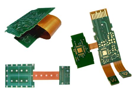
A Rigid-Flex PCB is a printed circuit board that combines both rigid and flexible substrates, allowing for enhanced design flexibility and improved reliability. This hybrid design enables the PCB to bend and fold, making it ideal for applications where space is limited or where the PCB needs to conform to a specific shape.
Advantages of Rigid-Flex PCBs
- Space Savings: Rigid-Flex PCBs allow for more compact designs, as the flexible sections can be folded or bent to fit into tight spaces.
- Improved Reliability: By eliminating the need for connectors and cables between rigid sections, Rigid-Flex PCBs reduce the risk of connection failures and improve overall reliability.
- Enhanced Design Flexibility: The combination of rigid and flexible substrates enables designers to create complex, three-dimensional shapes that would be impossible with traditional rigid PCBs.
- Reduced Weight: Rigid-Flex PCBs are generally lighter than their rigid counterparts, making them ideal for weight-sensitive applications such as aerospace and portable devices.
- Cost-Effective: Although the initial cost of a Rigid-Flex PCB may be higher than a traditional rigid PCB, the reduced assembly time and improved reliability can lead to overall cost savings in the long run.
RAYPCB’s Rigid-Flex PCB Manufacturing Process
At RAYPCB, we employ a highly refined manufacturing process to ensure the highest quality Rigid-Flex PCBs for our clients. Our process includes the following steps:
- Design Review: Our experienced engineers review the client’s design to ensure it meets all necessary requirements and standards.
- Material Selection: We select the appropriate materials for the rigid and flexible sections of the PCB based on the client’s specifications and the intended application.
- Lamination: The rigid and flexible layers are laminated together using advanced techniques to ensure a strong, reliable bond.
- Drilling and Plating: Holes are drilled through the PCB, and the walls of the holes are plated with copper to create electrical connections between layers.
- Etching: Unwanted copper is removed from the PCB using a precise etching process, leaving only the desired circuit patterns.
- Solder Mask Application: A protective solder mask is applied to the PCB to prevent short circuits and improve durability.
- Surface Finish: The exposed copper areas are coated with a surface finish, such as ENIG (Electroless Nickel Immersion Gold) or HASL (Hot Air Solder Leveling), to protect against oxidation and enhance solderability.
- Electrical Testing: Each Rigid-Flex PCB undergoes rigorous electrical testing to ensure it meets the client’s specifications and functions as intended.
- Visual Inspection: A final visual inspection is performed to check for any defects or irregularities before the PCBs are packaged and shipped to the client.

Applications of Rigid-Flex PCBs
Rigid-Flex PCBs are used in a wide variety of industries and applications, including:
- Aerospace and Defense: Rigid-Flex PCBs are well-suited for the harsh environments and strict reliability requirements of aerospace and defense applications.
- Medical Devices: The compact size and improved reliability of Rigid-Flex PCBs make them ideal for medical devices, such as wearable health monitors and implantable devices.
- Automotive Electronics: Rigid-Flex PCBs are increasingly used in automotive electronics, such as infotainment systems and advanced driver assistance systems (ADAS).
- Consumer Electronics: The space-saving and design flexibility benefits of Rigid-Flex PCBs are valuable in consumer electronics, such as smartphones, tablets, and wearable devices.
- Industrial Automation: Rigid-Flex PCBs are used in industrial automation applications, where their reliability and ability to withstand harsh environments are critical.

RAYPCB’s Rigid-Flex PCB Design Guidelines
To ensure the best performance and reliability of your Rigid-Flex PCBs, RAYPCB recommends following these design guidelines:
- Bend Radius: Ensure that the bend radius of the flexible sections is at least 10 times the thickness of the flexible material to minimize stress and prevent damage.
- Stiffener Placement: Use stiffeners in areas where the flexible section meets the rigid section to prevent excessive bending and improve reliability.
- Copper Balancing: Balance the copper distribution on both sides of the flexible layers to minimize warping and ensure consistent performance.
- Trace Width and Spacing: Use appropriate trace widths and spacing to accommodate the bending of the flexible sections and prevent signal integrity issues.
- Via Placement: Avoid placing vias in the bend areas of the flexible sections to prevent stress and potential failure.
| Rigid-Flex PCB Layer Configuration | Typical Applications |
|---|---|
| 2 Rigid Layers + 1 Flex Layer | Simple designs with limited flexibility requirements |
| 4 Rigid Layers + 2 Flex Layers | Moderate complexity designs with improved flexibility |
| 6 Rigid Layers + 3 Flex Layers | Complex designs with advanced flexibility and functionality |
| 8 Rigid Layers + 4 Flex Layers | Highly complex designs with maximum flexibility and performance |

RAYPCB’s Rigid-Flex PCB Materials
RAYPCB offers a wide range of materials for both the rigid and flexible sections of our Rigid-Flex PCBs. Some of the most common materials we use include:
Rigid Section Materials
- FR-4: A popular, cost-effective material with good mechanical and electrical properties.
- High Tg FR-4: An enhanced version of FR-4 with improved thermal stability and performance.
- Polyimide: A high-performance material with excellent thermal and chemical resistance.
- Rogers Materials: Advanced materials with superior high-frequency and low-loss properties.
Flexible Section Materials
- Polyimide (PI): The most widely used flexible substrate material, offering excellent thermal and mechanical properties.
- Polyester (PET): A cost-effective alternative to polyimide for less demanding applications.
- Flexible Copper Clad Laminate (FCCL): A laminate of copper foil and a flexible substrate material, used for creating the conductive layers in the flexible sections.
RAYPCB’s Rigid-Flex PCB Certifications and Standards
RAYPCB is committed to meeting the highest quality standards and certifications in the industry. Our Rigid-Flex PCBs are manufactured in accordance with the following standards and certifications:
- IPC-6013: The industry standard for Rigid-Flex PCB fabrication, covering materials, design, and manufacturing requirements.
- ISO 9001:2015: The international standard for quality management systems, ensuring consistent and reliable products and services.
- IATF 16949: The quality management system standard for the automotive industry, demonstrating our commitment to meeting the strict requirements of automotive customers.
- UL 94 V-0: A flammability rating that ensures our Rigid-Flex PCBs meet the highest fire safety standards.
- RoHS Compliant: Our Rigid-Flex PCBs are manufactured using materials that comply with the Restriction of Hazardous Substances (RoHS) directive.
Frequently Asked Questions (FAQ)
-
What is the minimum bend radius for a Rigid-Flex PCB?
The minimum bend radius for a Rigid-Flex PCB depends on the thickness of the flexible material. As a general rule, the bend radius should be at least 10 times the thickness of the flexible substrate to minimize stress and prevent damage. -
How many layers can a Rigid-Flex PCB have?
RAYPCB can manufacture Rigid-Flex PCBs with up to 8 rigid layers and 4 flexible layers. However, the number of layers will depend on the specific design requirements and the complexity of the application. -
What is the typical lead time for a Rigid-Flex PCB?
The lead time for a Rigid-Flex PCB can vary depending on the complexity of the design, the materials used, and the order quantity. Typically, lead times range from 2-4 weeks, but RAYPCB will work with you to determine a more accurate lead time based on your specific project requirements. -
Are Rigid-Flex PCBs more expensive than traditional rigid PCBs?
Yes, Rigid-Flex PCBs are generally more expensive than traditional rigid PCBs due to the additional materials and manufacturing processes involved. However, the cost savings associated with reduced assembly time, improved reliability, and space savings often outweigh the initial higher cost. -
Can RAYPCB assist with the design of my Rigid-Flex PCB?
Yes, RAYPCB’s experienced team of engineers can assist with the design of your Rigid-Flex PCB. We offer design review services and can provide guidance on material selection, bend radius, stiffener placement, and other critical design aspects to ensure the best performance and reliability of your Rigid-Flex PCB.
In conclusion, RAYPCB’s Rigid-Flex PCB service provides high-quality, reliable, and cost-effective solutions for a wide range of industries and applications. With our state-of-the-art manufacturing facilities, experienced engineering team, and commitment to meeting the highest quality standards and certifications, RAYPCB is your trusted partner for all your Rigid-Flex PCB needs.
No responses yet