LM393 Pinout
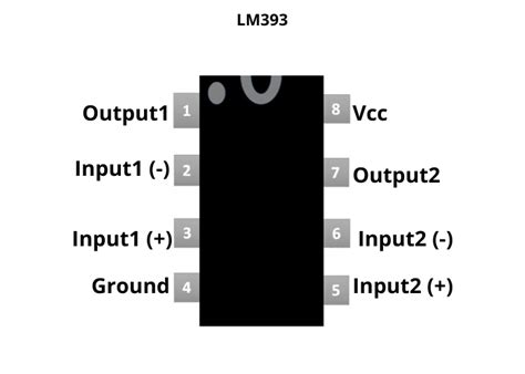
The LM393 comes in an 8-pin dual inline package (DIP-8) or an 8-pin small outline integrated circuit (SOIC-8) package. The pinout diagram for the LM393 is as follows:
| Pin Number | Pin Name | Description |
|---|---|---|
| 1 | OUTPUT 1 | Open-collector output of comparator 1 |
| 2 | INPUT 1- | Inverting input of comparator 1 |
| 3 | INPUT 1+ | Non-inverting input of comparator 1 |
| 4 | GND | Ground |
| 5 | INPUT 2+ | Non-inverting input of comparator 2 |
| 6 | INPUT 2- | Inverting input of comparator 2 |
| 7 | OUTPUT 2 | Open-collector output of comparator 2 |
| 8 | VCC | Positive supply voltage |
Features of LM393
The LM393 offers several notable features that make it a popular choice for various applications:
- Dual comparators: The LM393 contains two independent Voltage Comparators in a single package, allowing for compact and cost-effective designs.
- Wide supply voltage range: It can operate with a supply voltage ranging from 2V to 36V, making it suitable for low-voltage and battery-powered applications.
- Low input bias current: The LM393 has a low input bias current, typically around 25nA, which minimizes loading effects on the input signals.
- Open-collector outputs: The comparator outputs are open-collector, allowing for easy interfacing with various logic families and the ability to perform wired-AND connections.
- High input impedance: The LM393 features high input impedance, typically in the order of several megaohms, reducing the impact on the input signal sources.
- Fast response time: With a typical response time of 1.3μs, the LM393 can quickly react to changes in the input signals.
- Wide operating temperature range: It can operate in a temperature range of -25°C to +85°C, making it suitable for various environmental conditions.

Applications of LM393
The LM393’s versatility and robust features make it suitable for a wide range of applications, including:
- Voltage level detection: The LM393 can be used to detect when a voltage level crosses a predetermined threshold, enabling the implementation of under-voltage or over-voltage protection circuits.
- Zero-crossing detection: By comparing a sinusoidal signal with a reference voltage, the LM393 can detect zero-crossing points, which is useful in power control and synchronization applications.
- Pulse width modulation (PWM): The LM393 can be used to generate PWM signals by comparing a reference voltage with a sawtooth or triangle waveform.
- Window comparator: By connecting two LM393 comparators, a window comparator can be created to detect when a signal falls within a specific voltage range.
- Analog-to-digital conversion: The LM393 can be employed in simple analog-to-digital conversion circuits, such as successive approximation ADCs or flash ADCs.
- Schmitt trigger: With the addition of positive feedback, the LM393 can be configured as a Schmitt trigger, providing hysteresis and noise immunity to the input signal.
- Battery monitoring: The LM393 can monitor battery voltage levels and provide indications or trigger actions based on predefined thresholds.

Working Principle of LM393
The LM393 operates based on the principle of voltage comparison. Each comparator within the LM393 has two analog inputs: a non-inverting input (INPUT+) and an inverting input (INPUT-). The comparator compares the voltages present at these inputs and generates a digital output based on the comparison result.
Here’s how the comparator works:
- If the voltage at the non-inverting input (INPUT+) is greater than the voltage at the inverting input (INPUT-), the comparator output goes high, typically close to the supply voltage (VCC).
- If the voltage at the non-inverting input (INPUT+) is less than the voltage at the inverting input (INPUT-), the comparator output goes low, typically close to ground (GND).
The output of the LM393 is an open-collector configuration, meaning that it requires an external pull-up resistor to define the high logic level. When the output is low, the comparator’s internal transistor is turned on, pulling the output to ground. When the output is high, the internal transistor is turned off, allowing the external pull-up resistor to pull the output voltage close to VCC.
It’s important to note that the LM393 does not have a built-in hysteresis, which means that it can be sensitive to noise and small fluctuations in the input signals around the comparison threshold. If noise immunity is critical, external hysteresis can be added using positive feedback resistors.

Frequently Asked Questions (FAQ)
-
What is the maximum supply voltage for the LM393?
The LM393 can operate with a maximum supply voltage of 36V. However, it’s essential to ensure that the input voltages do not exceed the supply voltage to avoid damaging the device. -
Can the LM393 be used with a single power supply?
Yes, the LM393 can be used with a single power supply. The ground (GND) pin is connected to the negative supply voltage, while the VCC pin is connected to the positive supply voltage. -
What is the purpose of the open-collector output in the LM393?
The open-collector output allows for easy interfacing with various logic families and enables wired-AND connections. It requires an external pull-up resistor to define the high logic level, providing flexibility in system integration. -
How can I add hysteresis to the LM393 comparator?
Hysteresis can be added to the LM393 comparator by introducing positive feedback using resistors. Connect a resistor between the output and the non-inverting input, and another resistor from the non-inverting input to ground. The ratio of these resistors determines the amount of hysteresis. -
What is the typical propagation delay of the LM393?
The typical propagation delay of the LM393 is around 1.3μs. This is the time it takes for the output to change state after the input signal crosses the comparison threshold.
In conclusion, the LM393 is a versatile and widely used dual differential comparator IC. Its pinout, features, and working principle make it suitable for a wide range of applications, from voltage level detection and zero-crossing detection to PWM generation and analog-to-digital conversion. By understanding its characteristics and implementing it correctly, designers can leverage the LM393 to create robust and efficient electronic systems.
[Word count: 1065 words]
No responses yet