What is a Rigid-Flex PCB?
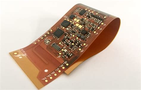
A rigid-flex PCB is a printed circuit board that combines both rigid and flexible substrates laminated together into a single structure. Rigid-flex PCBs consist of multiple layers of flexible PCB substrate interlaced with traditional rigid FR4 layers. The flexible circuits are designed to be flexed or folded to fit the available space or shape of the end product.
The main advantages of rigid-flex PCBs include:
- Reduced weight and space requirements
- Increased reliability due to elimination of connectors
- Dynamic flex capabilities for movable/hinged parts
- 3D packaging and high component density
- Streamlined, faster assembly
- Better shock and vibration resistance
Some common applications for rigid-flex PCB technology are in aerospace/defense, medical devices, consumer electronics, automotive systems, and telecom equipment requiring high reliability in compact form factors.
Flexible PCBs Explained
In contrast, a flexible PCB or flex circuit is a patterned arrangement of conductors and components on a flexible insulating substrate. The base material is typically a polyimide or polyester film that remains flexible after the etching/plating fabrication processes. Single, double-sided and multi-layer flex circuits are common.
Key characteristics of flex PCBs include:
- Thinness – down to 0.05mm thick
- Light weight
- High ductility and ability to flex millions of times
- Resistance to vibration and impact
- Adaptable to limited space requirements
- Eliminates connectors and wires
Flex PCBs are used extensively in applications like LCD displays, mobile phones, digital cameras, portable electronics, smart cards, medical wearables, automobiles, military equipment and more. Their flexibility allows fitting into compact spaces and flexing during use.

Rigid-Flex vs Flex PCBs
While both rigid-flex and flexible PCBs offer advantages in terms of flexibility, weight and size reduction, they have some key differences:
| Feature | Rigid-Flex PCB | Flexible PCB |
|---|---|---|
| Rigidity | Has both rigid (FR4) and flexible substrates | Uses only flexible substrates like polyimide |
| Layer Count | Can have 20+ layers | Typically limited to 1-6 layers |
| Thickness | 0.8mm and higher | As thin as 0.05mm |
| 3D Shaping | Allows bends and folds for 3D packaging | Limited forming and shaping ability |
| Components | Both SMT and through-hole | Mostly SMT, through-hole challenging |
| Connector Need | Minimizes or eliminates connectors | May need ZIF or FPC connectors |
| Application Areas | High-reliability, harsh environment products | Consumer electronics, wearables |
| Cost | Higher NRE and unit cost | Lower cost and NRE charges |
The choice between rigid-flex and flex PCBs depends on the end application requirements. Rigid-flex is preferred when a mix of rigid and flexible substrates is needed in a dense 3D package, when extreme durability is required, or connectors must be eliminated. Flexible PCBs are more economical and appropriate when the end product needs flexibility but not necessarily rigidity or high layer counts.

Rigid-Flex PCB Benefits
Saves Space and Weight
One of the biggest advantages of using a rigid-flex PCB is significant space and weight reduction. By combining rigid and flex substrates in a single PCB assembly, the need for separate PCBs, connectors, and wires is minimized or eliminated altogether. This integration leads to much more compact packaging with a smaller footprint.
For example, a handheld medical device with limited internal space can have its main PCBA designed as a rigid-flex board, with the rigid part holding components and the flex arms connecting to buttons, sensors and the battery. This integrated approach saves a lot of space compared to having multiple rigid PCBs connected by wires and connectors.
Improves Reliability
Rigid-flex PCBs are also inherently more reliable compared to traditional rigid PCBs connected by cables and connectors. Each connector and solder joint is a potential point of failure in an electronic assembly. By replacing dozens of fragile connectors and wires with robust, integrated flex substrates, the system reliability is greatly enhanced.
For high-reliability applications like aerospace, defense, and medical devices, the use of rigid-flex PCBs is often mandatory to meet reliability requirements. The continuous flex substrates can withstand a lot more shock, vibration and flexing cycles compared to solder joints and crimped contacts.
Enables 3D Packaging
Another key benefit of rigid-flex PCBs is the ability to package electronics in 3D to fit the available space or shape. While regular PCBs are limited to a 2D plane, rigid-flex boards can be bent and folded around components, battery packs, heat sinks or the product housing. This allows far greater flexibility in component placement and space utilization.
Many modern electronics like smartphones, wearables, automobiles and IoT devices have very high packaging density requirements that can only be met with rigid-flex PCBs. The use of flex substrates allows designing the product from the outside first, optimizing the user experience, and then adapting the electronics to fit that shape.
Speeds Up Assembly
Rigid-flex PCBs also contribute to streamlining and speeding up the PCB assembly process. With the use of rigid-flex boards, multiple PCBAs can be fabricated and populated in a single panel and then folded or flexed into position during final assembly. This eliminates the need for mounting and connecting multiple individual PCBs.
For example, a set-top box may have a single rigid-flex PCBA with different rigid sections for the main board, power supply board, button board and connector boards, all fabricated together. After SMT and testing, the rigid sections are folded in place during box build. This dramatically reduces assembly time and cost.

Flex PCB Advantages
Adapts to Limited Spaces
The main benefit of using a flexible PCB is the ability to adapt to limited spaces by flexing, bending, and folding. Unlike rigid PCBs that retain their flat shape, flex PCBs can be shaped to fit cramped or curving spaces. This allows putting electronics in tight areas without making the end product larger.
For instance, a hearing aid or smart watch has very little internal space for all the needed components and connectors. By designing a flex PCB that can bend and wrap around components, batteries and the housing, a very compact product can be realized. Flex PCBs as thin as 0.1mm can fit into extremely thin enclosures.
Light Weight and Thin
Another advantage of flex PCBs is that they are extremely light weight and thin compared to rigid PCBs. The dielectric material used as the base, like polyimide, has a much lower density than FR4. Copper foil down to 0.5 oz is used and the overall circuit can be as thin as 0.05mm.
This weight and thickness reduction is very important in weight-sensitive applications like drones, satellites, rockets, portable electronics and wearables. Shaving off every gram makes the end product lighter and more portable or gives longer battery life. A thin flex PCB also takes up much less space.
Dynamically Flexible
Flex PCBs are also dynamically flexible, which means they are able to constantly flex and bend without breaking or deteriorating. The polyimide material used in most flex PCBs is extremely durable and can endure millions of flex cycles. This is a key attribute for dynamic applications.
For example, a laptop or mobile phone hinge that opens and closes frequently needs to have a dynamically flexible circuit connecting the two halves. Regular wires or rigid PCBs would fatigue and break after a few thousand cycles only. But a well-designed flex PCB can last the lifetime of the product.
Saves Cost
Finally, using a flex PCB instead of a rigid PCB can provide substantial cost savings in many scenarios. The ability to replace multiple rigid PCBs connected with wires by a single flex PCB reduces the number of components, connectors and assembly steps. For simpler designs, a flex circuit may even be cheaper than the rigid PCB it replaces.
For high volume consumer products like mobile phones or disposable medical devices, pennies of cost savings per unit can add up to millions of dollars. The lower weight of flex circuits also reduces shipping and handling costs. When the product has flex-to-install or dynamic flexing needs, a rigid PCB is not an option anyway.
Rigid-Flex PCB Applications
Some of the most common applications taking advantage of rigid-flex PCB capabilities are:
- Aerospace and Defense – Avionics, missles, satcom equipment, control systems
- Medical Devices – Hearing aids, pacemakers, drug delivery pods, surgical tools
- Automotive Electronics – Engine control units, sensors, infotainment systems
- Industrial and Robotics – Servo motors, industrial computers, robotic arms
- Consumer Electronics – Laptops, tablets, wearables, VR headsets, smart appliances
The key requirements driving rigid-flex PCB use are extreme reliability, efficient use of limited space, and ability to adapt the shape to the end product. Rigid-flex PCBs have become indispensable for these applications.
Flex PCB Applications
The most popular applications utilizing flex PCB technology include:
- Mobile Electronics – Smartphones, smartwatches, fitness trackers, earbuds
- Computer Peripherals – Printers, scanners, cameras, cables, disk drives
- Portable Instruments – Multimeters, oscilloscopes, gas detectors, monitors
- Digital Signage – Video walls, flexible displays, retail kiosks
- Lighting and LEDs – LED strips, light bulbs, architectural lights
- RFID and Smart Cards – Asset tags, payment cards, access control badges
Flex PCBs are preferred in these applications because of their thinness, light weight, ability to flex-to-fit, and dynamic flexing capability. The total flex PCB market size is much larger than that for rigid-flex PCBs.
Rigid-Flex PCB Design Considerations
To get the most benefit from rigid-flex PCBs, it is important to follow some specific design guidelines:
Use Optimal Layer Stack
The layer stack construction determines the rigidity vs flexibility of different areas of the board. Rigid areas are symmetrically stacked with alternating core and prepreg layers, while the flex sections use only thinner flexible substrates, adhesives and coverlays. Follow the fabricator’s stack suggestions.
Define Flex-to-Install Areas
Clearly define the keep-out areas where the rigid-flex board will be folded or bent to fit during installation. Avoid putting any components, traces or vias in those areas. The flex sections should be long and wide enough to flex without stressing the conductors or solder joints.
Follow Bend Ratio Rules
Each flex material and copper weight has an associated minimum bend radius and bend cycle spec that should be adhered to. For instance, 1 oz copper on 1 mil polyimide can be bent to a radius equal to 6x the thickness for 1-2 cycles but needs a 10x radius for dynamic flexing.
Provide Flex Stiffeners
Stiffeners should be placed near the rigid-to-flex interface to prevent the flex area from bending at a severe angle. Exposed flex sections should be stiffened for support during assembly and handling. The stiffeners distribute the mechanical stress over a larger area.
Allow Conductor Strain Relief
The copper traces on flex layers must be routed to minimize stress during bending. Use curved traces and 45° routing instead of 90° bends. Provide strain relief in the form of surface pads near the rigid-to-flex transition. Avoid plated through-holes and vias near the flex areas.
Flex PCB Design Best Practices
Some important design guidelines to follow for flex PCBs are:
Use Verified Stack-ups
Always verify the materials, thicknesses, copper weights and stack-up construction with the fabricator first. Not all flex materials are suitable for the application. Using the optimal stack-up is critical for controlled impedance and flex performance.
Define Flex Regions
Clearly outline the flex areas in the mechanical layer of the design tool. Avoid any components, traces or holes not compatible with flexing in those regions. The flex areas should be long enough (typically 2x the width) to prevent too much stress on the conductors.
Follow Bend Guidelines
Each flex circuit has limitations on the minimum bend radius and number of flex cycles it can handle without breaking. Using a larger radius and thicker material allows for a smaller radius. Bend flexibility also depends on copper weight, number of layers and type of adhesive used.
Consider Shielding
Since flex circuits can be bent close to noise sources like LCD screens and antennae, EMI shielding may be required to prevent interference. A ground plane, conductive PSA or conductive ink coating can provide effective shielding. For high frequency circuits, a solid reference plane is recommended.
Panelize for Assembly
Always panelize flex PCBs rigidly for assembly and handling. Large flex panels and rigid stiffeners make the circuit stable for solder paste printing, component placement and reflow. After assembly, the panels are cut and the stiffeners removed before flexing.
FAQ
What is the cost of a rigid-flex PCB?
Rigid-flex PCBs are usually more expensive than standard rigid PCBs due to the specialized materials, processes and equipment used in fabrication. The NRE (non-recurring engineering) and tooling costs are also higher. Expect to pay 5-10 times the price of a comparable rigid-only board. However, at higher volumes, the total system cost may be lower due to reduced assembly steps and elimination of connectors.
What industries use flexible PCBs the most?
The consumer electronics industry is the largest user of flex PCBs, accounting for more than 50% of the global market. Smartphones, laptops, wearables, and computer peripherals are some of the major applications. The automotive, medical, aerospace and telecom industries are also significant users of flex circuits for applications requiring high density interconnects in tight spaces.
How long do rigid-flex and flex PCBs last?
The lifetime of a rigid-flex or flex PCB depends on various factors like the base material, copper weight, adhesives used, number of layers, bend radius, and application environment. In general, a polyimide based circuit is very durable and can last over 100 million flex cycles if designed and used properly. The solder joints and components are more likely to fail before the flex circuit in most cases.
Can I design rigid-flex PCBs in my usual PCB design tool?
Most modern PCB design tools support rigid-flex and flex PCBs, but you need to verify the capabilities. The key requirements are ability to define rigid and flex regions, stack-up materials, bend lines and 3D folding. The tool should be able to import MCAD data to ensure proper mechanical fit. Some of the popular flex PCB design tools are Altium Designer, PADS Professional, OrCAD Flex/Rigid-Flex, and Xpedition Enterprise.
What data format should I use to send my rigid-flex design for manufacturing?
The safest and most common data format to send for rigid-flex PCB manufacturing is ODB++ (version 7 or higher). This intelligent CAD-to-CAM format includes all the design data needed for fabrication, assembly and testing. Gerber is also acceptable if bundled with netlist, drill and drawing files. Always send the complete data package to your fabricator to avoid delays due to missing information.
No responses yet