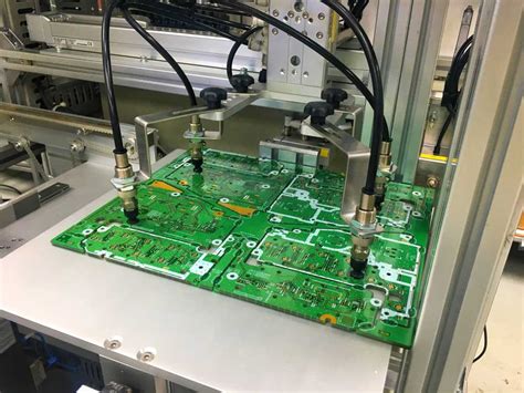
Introduction to PCB Milling
PCB milling is a process of creating custom printed circuit boards (PCBs) using a computer-controlled milling machine. This method allows for rapid prototyping and small-scale production of PCBs without the need for expensive and time-consuming chemical etching processes. In this comprehensive guide, we will walk you through the step-by-step process of creating your own PCB milling boards.
Benefits of PCB Milling
- Quick turnaround time for prototypes
- Cost-effective for small-scale production
- Allows for custom designs and modifications
- Environmentally friendly compared to chemical etching
Equipment and Materials Required
To get started with PCB milling, you will need the following equipment and materials:
- PCB milling machine
- Milling bits (end mills)
- PCB blanks (copper-clad boards)
- PCB design software
- Safety equipment (safety glasses, dust mask)
Choosing the Right PCB Milling Machine
When selecting a PCB milling machine, consider the following factors:
| Factor | Description |
|---|---|
| Work area | The size of the PCB you can create depends on the machine’s work area |
| Spindle speed | Higher spindle speeds allow for cleaner cuts and finer details |
| Resolution | Higher resolution machines produce more precise and accurate PCBs |
| Connectivity | Look for machines with USB or Ethernet connectivity for easy file transfer |
Some popular PCB milling machines include:
- Bantam Tools Desktop PCB Milling Machine
- Prometheus PCB Milling Machine
- Othermill Pro
- Carbide 3D Nomad 883 Pro
PCB Design Software
To create your PCB design, you will need specialized software. Some popular options include:
- Eagle PCB Design Software
- KiCad EDA
- Altium Designer
- Autodesk Fusion 360

Step-by-Step Guide to PCB Milling
Step 1: Create Your PCB Design
- Open your chosen PCB design software
- Create a new project and set the board dimensions
- Add components and traces to your design
- Ensure proper spacing and trace width for your chosen milling bit
- Export your design as a G-code file
Step 2: Prepare the PCB Milling Machine
- Install the appropriate milling bit for your design
- Secure the PCB blank to the machine’s work area
- Set the spindle speed and feed rate according to the manufacturer’s recommendations
- Zero the machine’s coordinates to ensure accurate milling
Step 3: Mill the PCB
- Load the G-code file into the PCB milling machine’s software
- Start the milling process
- Monitor the progress and make adjustments if necessary
- Once complete, remove the milled PCB from the machine
Step 4: Clean and Inspect the PCB
- Carefully remove any debris or dust from the PCB using a brush or compressed air
- Inspect the PCB for any defects or errors
- Use a multimeter to test for continuity and short circuits
Step 5: Assemble and Test the PCB
- Solder components onto the PCB according to your design
- Double-check component placement and orientation
- Test the assembled PCB for proper functionality
Tips and Tricks for Successful PCB Milling
- Always wear safety equipment when operating the milling machine
- Use high-quality PCB blanks for best results
- Regularly clean and maintain your milling machine and bits
- Double-check your design before milling to avoid costly mistakes
- Start with simple designs and gradually increase complexity as you gain experience
Troubleshooting Common PCB Milling Issues
| Issue | Solution |
|---|---|
| Broken milling bits | Reduce spindle speed or feed rate, ensure proper bit installation |
| Uneven or rough cuts | Adjust spindle speed and feed rate, check for debris on the PCB or bit |
| Inaccurate milling | Recalibrate the machine’s coordinates, ensure proper G-code file |
| Incomplete cuts | Check milling depth, ensure sufficient clearance between the bit and PCB |
FAQ
-
Q: How long does it take to mill a PCB?
A: The time required to mill a PCB depends on the complexity of the design and the size of the board. Simple designs can be milled in under an hour, while more complex boards may take several hours. -
Q: Can I use any material for PCB milling?
A: PCB milling typically uses copper-clad boards, which consist of a fiberglass substrate with a layer of copper on one or both sides. Other materials, such as aluminum or brass, can be used for specialized applications but may require different milling bits and settings. -
Q: What is the minimum trace width and spacing for PCB milling?
A: The minimum trace width and spacing depend on the capabilities of your milling machine and the size of the milling bit. Generally, trace widths and spacing of 0.2 mm to 0.5 mm are achievable with most PCB milling machines. -
Q: Can I mill double-sided PCBs?
A: Yes, double-sided PCBs can be milled using a PCB milling machine. However, it requires a more complex design process and precise alignment of the two sides of the board. Some PCB milling machines have built-in features to assist with double-sided milling. -
Q: How do I choose the right milling bit for my PCB design?
A: The choice of milling bit depends on the trace width, spacing, and depth required for your PCB design. Smaller bits (0.1 mm to 0.5 mm) are used for finer details and narrower traces, while larger bits (0.5 mm to 1.0 mm) are used for wider traces and larger components. Consult your milling machine’s documentation or the bit manufacturer’s recommendations for specific guidance.
Conclusion
PCB milling is a powerful and accessible method for creating custom printed circuit boards. By following this step-by-step guide and investing in the right equipment and materials, you can quickly and efficiently produce high-quality PCBs for your projects. As you gain experience with PCB milling, you’ll be able to take on more complex designs and explore the full potential of this versatile fabrication technique.

No responses yet