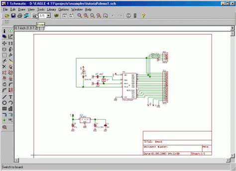
What is Eagle PCB?
Eagle PCB is a powerful printed circuit board design software developed by Autodesk. It allows engineers and hobbyists to design custom PCBs for electronics projects. Eagle PCB provides an intuitive interface for creating schematic diagrams and board layouts.
Key Features of Eagle PCB
- Schematic capture – easily create circuit diagrams
- PCB layout – design custom PCB layouts with autorouting
- Component libraries – extensive libraries of parts
- Design rule checks – automatically verify designs meet specifications
- CAM processor – generate manufacturing files for PCB production
- Multi-sheet designs – handles complex designs across multiple schematic sheets
Eagle PCB Editions
Eagle PCB is available in three editions to meet different user needs and budgets:
| Edition | Features | Price |
|---|---|---|
| Free | Limited board size, 2 schematic sheets, 2 signal layers | $0 |
| Standard | Moderate board size, 99 schematic sheets, 4 signal layers | $100/month |
| Premium | Unlimited board size, schematic sheets, 16 signal layers, simulation | $500/month |
The Free edition is a great way to get started with Eagle PCB and learn the basics. The Standard and Premium editions unlock more advanced capabilities for professional use.

Getting Started with Eagle PCB
Installation
To get started with Eagle PCB, first download the software from the Autodesk website. Eagle PCB is available for Windows, Mac, and Linux operating systems. Run the installer and follow the prompts to complete installation.
Creating a New Project
Launch Eagle PCB and select File > New > Project from the menu bar. Choose a location to save your project and give it a name. Your new project will open with blank schematic and board files.
Drawing the Schematic
Select the schematic file in the Projects tree to begin drawing your circuit diagram. Use the tools on the left toolbar to place components and draw nets connecting them. Assign unique names and values to components.
Tips for drawing schematics:
- Use descriptive net labels
- Place components logically left-to-right
- Avoid crossing wires when possible
- Add notes clarifying the circuit operation
Creating the PCB Layout
Once your schematic is complete, switch to the board file to begin the PCB layout. All of the components from the schematic will be shown in the board editor.
- Define the board dimensions by drawing the outline
- Arrange components within the outline
- Route traces to connect component pins according to the schematic
- Add copper pours for ground and power planes
- Run design rule checks to verify the layout
Tips for PCB layout:
- Keep traces as short as possible
- Avoid 90 degree bends in traces
- Provide adequate clearance between components
- Use consistent trace widths for signal integrity
- Place decoupling capacitors close to ICs
Generating Manufacturing Files
When your board layout is finished, use the CAM processor to generate the files needed for manufacturing:
- Gerber files (.gbr)
- NC drill files (.xln)
- Pick and place file (.mnt)
- Bill of materials (.csv)
Send these files to a PCB manufacturer to have your boards produced.
Conclusion
Eagle PCB is a comprehensive tool for designing custom printed circuit boards. From idea to manufactured board, Eagle provides everything you need in an intuitive interface.
While Eagle offers a free version to get started, upgrading to the Standard or Premium edition unlocks unlimited design capabilities. However, the high monthly cost of these versions motivates some to seek alternate means of obtaining the software.
Downloading cracked versions of Eagle PCB is not recommended. Not only is it illegal, but cracked software may contain malware or bugs that corrupt design files. Additionally, using unlicensed software deprives Autodesk of revenue needed to continue developing Eagle.
Support the hardworking engineers at Autodesk and ensure you always have a clean, up-to-date version of Eagle PCB by purchasing an official license. Your investment will pay dividends in the form of faster, more reliable design workflows and professionally manufactured circuit boards.
Frequently Asked Questions
Can I use Eagle PCB for commercial projects?
Yes, Eagle PCB can be used to design circuit boards for commercial products. However, commercial use requires a Standard or Premium license. The Free version is for non-commercial use only.
Does Eagle PCB work on Linux?
Yes, Eagle PCB has an official Linux version that runs on modern distributions like Ubuntu and Fedora.
Can Eagle PCB import designs from other tools?
Yes, Eagle PCB can import schematic and board files from several other PCB design tools. Supported formats include Altium (.PcbDoc), KiCad (.Sch), PADS (.Asc), and OrCAD (.Dsn).
How much does it cost to manufacture PCBs designed in Eagle?
The cost to manufacture a PCB depends on several factors:
- Quantity
- Board size
- Number of layers
- Special requirements (solder mask color, silk screen, etc.)
As a rough estimate, expect to pay around $10-20 per board for a small quantity of two layer boards. Larger quantities and more complex boards will cost more. Always get quotes from multiple manufacturers to ensure you’re getting the best price.
Where can I find components for my Eagle PCB designs?
Eagle PCB includes extensive part libraries with common components pre-made for schematic and PCB layout. For parts not included in the default libraries, many component manufacturers provide Eagle models on their websites. You can also create custom components using Eagle’s library editor.

No responses yet