Introduction to Colpitts Oscillator
A Colpitts oscillator is a type of electronic oscillator circuit that generates sinusoidal signals using a combination of inductors and capacitors. It is named after its inventor, Edwin Colpitts, who developed the circuit in 1918. The Colpitts oscillator is widely used in various electronic applications due to its simplicity, stability, and ability to generate high-frequency signals.
Basic Principle of Operation
The basic principle behind the Colpitts oscillator is the use of a resonant LC tank circuit to generate oscillations. The tank circuit consists of an inductor (L) and two capacitors (C1 and C2) connected in series. The capacitors form a voltage divider, and the junction between them provides positive feedback to the active device, typically a bipolar junction transistor (BJT) or a field-effect transistor (FET).
The oscillations in a Colpitts oscillator are sustained by the energy exchange between the inductor and the capacitors. The frequency of oscillation is determined by the values of the inductor and capacitors, and can be calculated using the following formula:
f = 1 / (2π√(LC))
where:
– f is the frequency of oscillation in hertz (Hz)
– L is the inductance in henries (H)
– C is the equivalent capacitance of C1 and C2 in farads (F), given by:
C = (C1 * C2) / (C1 + C2)
Advantages of Colpitts Oscillator
The Colpitts oscillator offers several advantages over other types of oscillator circuits:
-
Simplicity: The Colpitts oscillator requires fewer components compared to other oscillator circuits, making it relatively simple to design and construct.
-
Frequency stability: The Colpitts oscillator exhibits good frequency stability, especially when using high-quality components and proper circuit layout techniques.
-
Wide frequency range: By selecting appropriate values for the inductor and capacitors, the Colpitts oscillator can generate signals over a wide range of frequencies, from a few kilohertz to several hundred megahertz.
-
Low distortion: The Colpitts oscillator can produce signals with low harmonic distortion, making it suitable for applications that require clean sinusoidal waveforms.
-
Easy to tune: The frequency of a Colpitts oscillator can be easily adjusted by varying the values of the capacitors or the inductor, allowing for fine-tuning of the output frequency.
Circuit Design and Analysis
Basic Colpitts Oscillator Circuit
A basic Colpitts oscillator circuit consists of the following components:
- An inductor (L)
- Two capacitors (C1 and C2)
- An active device (BJT or FET)
- Bias resistors (R1 and R2)
- A coupling capacitor (CC)
- A load resistor (RL)
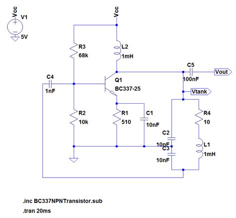
Here’s a schematic diagram of a basic Colpitts oscillator circuit using a BJT:
           +VCC
            |
            |
           R1
            |
            |
           +|
      C1   |    L
      ||---+---mmm---+
      ||            |
      ||            |
      ||---+        |
      ||   |        |
     C2    |        |
      |    +--------+
    +---+--|        |
    |   |  |        |
    |  R2  |       RL
    |   |  |        |
    +---+--+        |
       |            |
      GND          GND
In this circuit:
– The LC tank circuit is formed by L, C1, and C2.
– The BJT acts as the active device, providing amplification and positive feedback.
– R1 and R2 form a voltage divider to bias the BJT.
– CC is the coupling capacitor, which blocks DC and allows AC signals to pass through.
– RL is the load resistor, which determines the output impedance and power of the oscillator.
Circuit Analysis
To analyze the Colpitts oscillator circuit, we can use Kirchhoff’s voltage law (KVL) and Kirchhoff’s current law (KCL) to derive the necessary equations.
Applying KVL to the LC tank circuit:
VL + VC1 + VC2 = 0
where:
– VL is the voltage across the inductor
– VC1 is the voltage across capacitor C1
– VC2 is the voltage across capacitor C2
Applying KCL at the junction of C1, C2, and the BJT:
IC1 + IC2 + IB = 0
where:
– IC1 is the current through capacitor C1
– IC2 is the current through capacitor C2
– IB is the base current of the BJT
Using these equations and the component values, we can determine the oscillation frequency, gain, and other circuit parameters.
Oscillation Startup Conditions
For the Colpitts oscillator to start and sustain oscillations, certain conditions must be met:
-
Loop gain: The loop gain, which is the product of the amplifier gain and the feedback factor, must be greater than or equal to 1 at the oscillation frequency.
-
Phase shift: The total phase shift around the feedback loop must be an integer multiple of 360° (or 0°) at the oscillation frequency.
-
Barkhausen stability criterion: The Barkhausen stability criterion states that the magnitude of the loop gain must be exactly 1, and the phase shift must be an integer multiple of 360° for sustained oscillations.
Practical Considerations
When designing and constructing a Colpitts oscillator circuit, several practical considerations should be taken into account:
-
Component selection: Use high-quality, stable components to ensure good frequency stability and low noise. The inductor should have a high Q factor, and the capacitors should have low temperature coefficients.
-
Parasitic effects: Consider the parasitic effects of the components, such as the series resistance of the inductor and the equivalent series resistance (ESR) of the capacitors, which can affect the oscillator’s performance.
-
Layout: Proper circuit layout is crucial to minimize stray capacitances, inductances, and coupling between components. Keep the lead lengths short, and use ground planes to reduce noise and interference.
-
Power supply decoupling: Use adequate power supply decoupling techniques, such as bypass capacitors, to minimize supply voltage fluctuations and noise.
-
Output buffering: If the oscillator is required to drive a load or interface with other circuits, use an output buffer stage to isolate the oscillator from the load and prevent loading effects from altering the oscillation frequency.

Applications of Colpitts Oscillator
The Colpitts oscillator finds numerous applications in various fields of electronics, such as:
Radio Frequency (RF) Circuits
Colpitts oscillators are commonly used in RF circuits for generating carrier signals, local oscillator signals, and clock signals. They are employed in:
- AM and FM Transmitters and receivers
- Wireless communication systems
- Radar and navigation systems
- RF test and measurement equipment
Audio and Ultrasonic Applications
Colpitts oscillators can be designed to operate at audio and ultrasonic frequencies, making them suitable for:
- Electronic musical instruments
- Sonar systems
- Ultrasonic cleaning and welding equipment
- Medical ultrasound imaging devices
Sensor and Instrumentation
Colpitts oscillators are used in sensor and instrumentation applications, such as:
- Capacitive and inductive sensor excitation and detection
- Proximity and level sensing
- Temperature and pressure measurement
- Electronic weighing scales
Clock Generation and Timing Circuits
Colpitts oscillators can be used to generate clock signals and timing references in:
- Digital systems and microcontrollers
- Frequency synthesizers and phase-locked loops (PLLs)
- Timers and counters
- Switching power supplies

Variations and Modifications
Several variations and modifications of the basic Colpitts oscillator circuit exist, each offering specific advantages or addressing certain limitations:
Hartley-Colpitts Oscillator
The Hartley-Colpitts oscillator is a hybrid circuit that combines features of both the Hartley and Colpitts oscillators. It uses a tapped inductor and a single capacitor to form the LC tank circuit. This configuration offers improved frequency stability and easier tuning compared to the basic Colpitts oscillator.
Clapp Oscillator
The Clapp oscillator, also known as the series-tuned Colpitts oscillator, is a modification that adds a series-tuned LC circuit in parallel with one of the capacitors in the feedback network. This additional LC circuit helps to reduce the effect of the active device’s capacitance on the oscillation frequency, improving frequency stability.
Crystal-Controlled Colpitts Oscillator
A crystal-controlled Colpitts oscillator uses a quartz crystal as the frequency-determining element instead of an LC tank circuit. The crystal provides excellent frequency stability and accuracy, making it suitable for applications that require precise frequency control, such as in frequency standards and reference oscillators.
Voltage-Controlled Colpitts Oscillator (VCCO)
A voltage-controlled Colpitts oscillator (VCCO) incorporates a varactor diode in parallel with one of the capacitors in the tank circuit. By applying a variable DC voltage to the varactor, its capacitance can be varied, allowing the oscillation frequency to be electronically tuned. VCCOs are used in applications such as voltage-controlled oscillators (VCOs) and frequency modulators.

Troubleshooting and Optimization
When working with Colpitts oscillators, you may encounter various issues that affect their performance. Here are some common problems and their solutions:
Oscillator Not Starting
If the oscillator fails to start, check the following:
- Verify that the DC bias conditions are correct and the active device is properly biased.
- Ensure that the loop gain is sufficient to sustain oscillations. Adjust the component values or the feedback network if necessary.
- Check for any faulty components, such as a damaged inductor or leaky capacitors.
Frequency Drift
If the oscillator’s frequency drifts over time or with temperature changes:
- Use high-quality, temperature-stable components, such as NP0 or C0G capacitors and low-temperature-coefficient inductors.
- Ensure proper power supply regulation and decoupling to minimize the effect of supply voltage variations on the oscillation frequency.
- Consider using a crystal-controlled Colpitts oscillator for applications that require high frequency stability.
Poor Waveform Quality
If the oscillator’s output waveform exhibits distortion or excessive harmonics:
- Ensure that the active device is operating in its linear region and not saturating or cutting off.
- Use a high-Q inductor and low-loss capacitors to minimize the effect of component non-idealities on the waveform.
- Adjust the bias conditions and feedback network to optimize the waveform shape.
- Consider adding a buffer stage or a low-pass filter at the output to reduce harmonics and improve waveform purity.
Amplitude Instability
If the oscillator’s output amplitude varies or is unstable:
- Use a well-regulated and noise-free power supply to minimize the effect of supply voltage fluctuations on the output amplitude.
- Ensure that the active device is not overloaded or driven into saturation, which can cause amplitude compression.
- Consider using automatic gain control (AGC) techniques or a limiter circuit to stabilize the output amplitude.
Conclusion
The Colpitts oscillator is a versatile and widely used circuit for generating sinusoidal signals in various electronic applications. Its simplicity, stability, and wide frequency range make it an attractive choice for designers and engineers.
By understanding the basic principles, circuit design, and practical considerations of Colpitts oscillators, you can effectively implement them in your projects and optimize their performance to meet specific requirements.
As with any electronic circuit, proper component selection, layout, and troubleshooting techniques are essential to ensure reliable and efficient operation of Colpitts oscillators.
Frequently Asked Questions (FAQ)
- Q: What is the main difference between a Colpitts oscillator and a Hartley oscillator?
A: The main difference lies in the way the feedback network is constructed. In a Colpitts oscillator, the feedback network consists of two capacitors and an inductor, with the capacitors forming a voltage divider. In a Hartley oscillator, the feedback network consists of a tapped inductor and a single capacitor.
- Q: Can a Colpitts oscillator be used for generating square waves?
A: While a Colpitts oscillator is primarily designed to generate sinusoidal signals, it can be modified to produce square waves by adding a non-linear element, such as a Schmitt trigger or a comparator, at the output stage. However, for generating square waves, other oscillator topologies, such as the astable multivibrator, are more commonly used.
- Q: How does the choice of active device (BJT or FET) affect the performance of a Colpitts oscillator?
A: The choice of active device can affect the oscillator’s performance in terms of frequency range, output power, and noise characteristics. BJTs are generally preferred for low-frequency and high-power applications, while FETs are often used for high-frequency and low-noise applications. The active device’s input and output capacitances also influence the oscillation frequency and must be considered during the design process.
- Q: What is the purpose of the coupling capacitor (CC) in a Colpitts oscillator circuit?
A: The coupling capacitor (CC) serves two purposes in a Colpitts oscillator circuit. First, it blocks the DC bias voltage from reaching the output, ensuring that only the AC signal is passed through. Second, it acts as a high-pass filter, attenuating any low-frequency noise or harmonics present in the output signal.
- Q: How can the oscillation frequency of a Colpitts oscillator be adjusted?
A: The oscillation frequency of a Colpitts oscillator can be adjusted by varying the values of the inductor (L) or the capacitors (C1 and C2) in the tank circuit. This can be achieved by using variable capacitors or inductors, or by switching between different fixed-value components using relays or electronic switches. In some cases, a varactor diode can be used to electronically tune the oscillation frequency by varying the applied DC voltage.
No responses yet