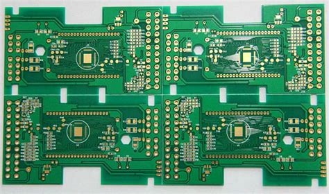
What is PCB Etching?
PCB etching is a subtractive process that removes unwanted copper from a copper-clad substrate, leaving behind the desired conductive patterns. The process typically involves applying a resist layer to the copper surface, which is then selectively removed to expose the areas to be etched. The exposed copper is then chemically or mechanically removed, while the resist-protected areas remain intact.
The Importance of PCB Etching
PCB etching plays a vital role in the production of high-quality and reliable printed circuit boards. The process ensures that the conductive pathways are accurately created according to the design specifications, enabling the proper functioning of electronic devices. Some key benefits of PCB etching include:
- Creating precise and intricate conductive patterns
- Ensuring electrical continuity and signal integrity
- Facilitating the miniaturization of electronic devices
- Enabling mass production of PCBs with consistent quality
Types of PCB Etching Methods
There are several methods used for PCB etching, each with its own advantages and limitations. The choice of etching method depends on factors such as the desired feature size, production volume, and available resources. Let’s explore the most common PCB etching methods:
Chemical Etching
Chemical etching is the most widely used method for PCB etching. It involves the use of chemical etchants, typically acidic solutions, to dissolve the exposed copper. The most common etchant used in the industry is ferric chloride (FeCl₃). Other etchants include ammonium persulfate ((NH₄)₂S₂O₈) and cupric chloride (CuCl₂).
Advantages of Chemical Etching
- Relatively low cost
- Suitable for high-volume production
- Can achieve fine feature sizes (down to ~0.1mm)
Disadvantages of Chemical Etching
- Requires careful handling and disposal of hazardous chemicals
- Can be time-consuming for thick copper layers
- May result in undercutting of features
Mechanical Etching
Mechanical etching, also known as abrasive etching, uses physical means to remove the unwanted copper. This method typically employs abrasive particles, such as sand or alumina, propelled by compressed air to blast away the exposed copper. Mechanical etching is less common compared to chemical etching but finds applications in certain specialized fields.
Advantages of Mechanical Etching
- Environmentally friendly (no hazardous chemicals)
- Can handle thick copper layers effectively
- Minimal undercutting of features
Disadvantages of Mechanical Etching
- Limited feature resolution compared to chemical etching
- Higher equipment and operating costs
- Slower production rates
Laser Etching
Laser etching is a advanced method that uses high-energy laser beams to vaporize the unwanted copper. This method offers high precision and can create extremely fine features. Laser etching is particularly useful for producing high-density interconnect (HDI) PCBs and micro-vias.
Advantages of Laser Etching
- High precision and resolution (features down to ~0.05mm)
- Minimal undercutting and superior edge definition
- Rapid processing times
Disadvantages of Laser Etching
- High equipment and operating costs
- Limited to small-scale production or prototyping
- May require specialized substrate materials

The PCB Etching Process
The PCB etching process typically involves several steps, from substrate preparation to the final etching and cleaning. Let’s go through each step in detail:
Step 1: Substrate Preparation
The first step is to prepare the copper-clad substrate. This involves cleaning the surface to remove any contaminants, such as dirt, grease, or oxidation. Common cleaning methods include chemical cleaning (e.g., using solvents or alkaline solutions) or mechanical cleaning (e.g., scrubbing or abrasion).
Step 2: Applying the Resist
Once the substrate is clean, a resist layer is applied to the copper surface. The resist acts as a protective mask, selectively exposing the areas to be etched. There are two main types of resists:
-
Photoresist: A light-sensitive material that is exposed and developed using UV light and a photomask. Photoresists can be positive (exposed areas become soluble) or negative (exposed areas become insoluble).
-
Etch resist ink: A ink-based resist that is applied directly to the copper surface using a silk-screen or inkjet printing process.
The choice of resist depends on the desired feature size, resolution, and production volume.
Step 3: Patterning the Resist
After applying the resist, it needs to be patterned according to the PCB design. For photoresists, this involves aligning a photomask with the desired pattern over the resist-coated substrate and exposing it to UV light. The exposed areas undergo a chemical change, making them either soluble (positive resist) or insoluble (negative resist) in a developing solution.
For etch resist inks, the patterning is achieved directly during the application process, either by selective screen printing or inkjet printing.
Step 4: Developing the Resist
In the case of photoresists, the next step is to develop the exposed resist. The substrate is immersed in a developing solution, which selectively removes either the exposed (positive resist) or unexposed (negative resist) areas. This process reveals the copper areas to be etched.
Etch resist inks do not require a separate developing step.
Step 5: Etching the Copper
With the resist pattern in place, the substrate is ready for etching. The choice of etching method (chemical, mechanical, or laser) depends on the specific requirements and available resources.
For chemical etching, the substrate is immersed in an etchant solution, such as ferric chloride. The etchant chemically dissolves the exposed copper, while the resist-protected areas remain intact. The etching time depends on factors such as the copper thickness, etchant concentration, and temperature.
Mechanical and laser etching follow their respective processes, selectively removing the exposed copper through physical abrasion or laser vaporization.
Step 6: Removing the Resist
After etching, the remaining resist layer needs to be removed to reveal the final copper pattern. This is typically done using a resist stripper solution, which chemically dissolves the resist without affecting the underlying copper.
Step 7: Cleaning and Inspection
The final step is to thoroughly clean the etched PCB to remove any residual etchant or resist residues. This can be done using deionized water and a mild cleaning agent. The PCB is then dried and inspected for any defects or discrepancies in the etched pattern.

Factors Affecting PCB Etching Quality
Several factors can influence the quality and accuracy of PCB etching. Understanding and controlling these factors is essential for achieving optimal results. Some key factors include:
-
Copper thickness: Thicker copper layers require longer etching times and may be more prone to undercutting.
-
Etchant concentration and temperature: Higher etchant concentrations and temperatures generally lead to faster etching rates but may compromise feature resolution.
-
Resist quality and adhesion: A high-quality resist with good adhesion to the copper surface is crucial for achieving well-defined features and minimizing undercutting.
-
Agitation: Proper agitation of the etchant solution helps maintain a uniform etching rate and prevents the build-up of etch by-products.
-
Etch factor: The etch factor, which is the ratio of the lateral etch rate to the vertical etch rate, determines the degree of undercutting. A lower etch factor results in more vertical sidewalls and better feature resolution.

Advances in PCB Etching Technology
PCB etching technology continues to evolve, driven by the demand for smaller, more complex, and high-performance electronic devices. Some notable advances include:
-
Direct Imaged Resists (DIR): DIR technology allows for the direct patterning of resists using digital imaging systems, eliminating the need for photomasks. This enables faster turnaround times and greater design flexibility.
-
Laser Direct Imaging (LDI): LDI uses high-precision lasers to directly expose the resist, achieving finer feature resolutions and improved registration accuracy compared to conventional UV exposure methods.
-
Plasma Etching: Plasma etching uses ionized gases to selectively remove copper, offering superior etch uniformity and control compared to traditional wet chemical etching.
-
Inkjet Etching Resists: The development of inkjet-compatible etching resists has opened up new possibilities for rapid prototyping and low-volume production of PCBs.
These advances have significantly improved the capabilities and efficiency of PCB etching, enabling the fabrication of more advanced and miniaturized electronic devices.
FAQ
-
Q: What is the most common etchant used for PCB etching?
A: The most common etchant used in the PCB industry is ferric chloride (FeCl₃). It is an acidic solution that chemically dissolves copper. -
Q: What is the difference between positive and negative photoresists?
A: Positive photoresists become soluble in the exposed areas when subjected to UV light, while negative photoresists become insoluble in the exposed areas. The choice between the two depends on the specific application and process requirements. -
Q: How can I minimize undercutting during PCB etching?
A: To minimize undercutting, you can use a high-quality resist with good adhesion, optimize the etchant concentration and temperature, and ensure proper agitation during the etching process. Using a lower etch factor also helps in achieving more vertical sidewalls. -
Q: Can I etch a PCB at home?
A: Yes, it is possible to etch PCBs at home using simple methods like toner transfer and ferric chloride etching. However, it is essential to follow proper safety precautions and dispose of the chemical waste responsibly. -
Q: What are the environmental concerns associated with PCB etching?
A: PCB etching, particularly chemical etching, involves the use of hazardous chemicals that can pose risks to human health and the environment if not handled and disposed of properly. It is crucial to follow appropriate safety protocols and comply with local regulations regarding the use and disposal of these chemicals.
Conclusion
PCB etching is a vital process in the manufacturing of printed circuit boards, enabling the creation of precise and intricate conductive patterns. The choice of etching method, be it chemical, mechanical, or laser, depends on the specific requirements and constraints of the project. Understanding the steps involved in PCB etching, from substrate preparation to final cleaning, is essential for achieving high-quality results.
As technology advances, new techniques and materials are being developed to improve the efficiency, resolution, and environmental sustainability of PCB etching. By staying informed about these advancements and best practices, PCB manufacturers can continue to push the boundaries of what is possible in the realm of electronic device fabrication.
| Etching Method | Advantages | Disadvantages |
|---|---|---|
| Chemical Etching | – Relatively low cost – Suitable for high-volume production – Can achieve fine feature sizes |
– Requires careful handling and disposal of hazardous chemicals – Can be time-consuming for thick copper layers – May result in undercutting of features |
| Mechanical Etching | – Environmentally friendly – Can handle thick copper layers effectively – Minimal undercutting of features |
– Limited feature resolution compared to chemical etching – Higher equipment and operating costs – Slower production rates |
| Laser Etching | – High precision and resolution – Minimal undercutting and superior edge definition – Rapid processing times |
– High equipment and operating costs – Limited to small-scale production or prototyping – May require specialized substrate materials |
No responses yet