Introduction to the Arduino Pro Micro
The Arduino Pro Micro is a development board designed and manufactured by SparkFun Electronics. It features the ATmega32U4 microcontroller, which is known for its built-in USB communication capabilities. The board’s compact size of 33mm x 18mm makes it suitable for projects with limited space requirements.
Key Features of the Arduino Pro Micro
- ATmega32U4 microcontroller running at 5V/16MHz or 3.3V/8MHz
- 12 digital input/output pins
- 4 analog input pins
- Hardware serial, I2C, and SPI support
- Built-in USB communication (no need for a separate USB-to-serial converter)
- Lightweight and compact design
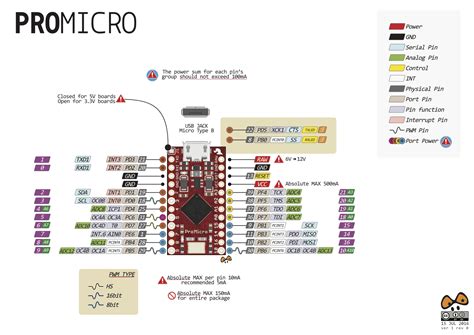
Arduino Pro Micro Pinout Diagram
To effectively work with the Arduino Pro Micro, it is essential to understand its pinout. The following diagram illustrates the location and labeling of the pins on the board:
[Insert pinout diagram image here]

Digital I/O Pins
The Arduino Pro Micro features 12 digital input/output (I/O) pins, labeled D0 to D11. These pins can be used for various purposes, such as reading sensors, controlling actuators, or communicating with other devices.
Digital Pin Capabilities
| Pin | Function | Notes |
|---|---|---|
| D0 | RX | Serial receive (input) |
| D1 | TX | Serial transmit (output) |
| D2 | SDA | I2C data line |
| D3 | SCL | I2C clock line |
| D4 | A6 | Analog input (ADC6) |
| D5 | PWM | Pulse Width Modulation output |
| D6 | A7 | Analog input (ADC7) |
| D7 | PWM | Pulse Width Modulation output |
| D8 | A8 | Analog input (ADC8) |
| D9 | A9 | Analog input (ADC9), PWM output |
| D10 | A10 | Analog input (ADC10), PWM output |
| D11 | PWM | Pulse Width Modulation output |
Pulse Width Modulation (PWM) Pins
Pins D5, D7, D9, D10, and D11 support Pulse Width Modulation (PWM) output. PWM allows you to generate analog-like signals by varying the duty cycle of a digital signal. This is particularly useful for controlling the brightness of LEDs or the speed of motors.

Analog Input Pins
The Arduino Pro Micro has 4 analog input pins, labeled A6 to A9. These pins can read analog voltage levels and convert them into digital values using the onboard Analog-to-Digital Converter (ADC). The ADC has a resolution of 10 bits, meaning it can detect 1,024 different voltage levels (0-1023).
Analog Pin Capabilities
| Pin | Function | Notes |
|---|---|---|
| A6 | D4 | Digital I/O (ADC6) |
| A7 | D6 | Digital I/O (ADC7) |
| A8 | D8 | Digital I/O (ADC8) |
| A9 | D9 | Digital I/O (ADC9), PWM output |

Communication Protocols
The Arduino Pro Micro supports various communication protocols, enabling it to interact with other devices and sensors.
Serial Communication (UART)
The Pro Micro has a hardware serial port (UART) for serial communication. Pins D0 (RX) and D1 (TX) are used for receiving and transmitting serial data, respectively. This allows the Pro Micro to communicate with other devices, such as computers, GPS modules, or Bluetooth modules.
I2C (Inter-Integrated Circuit)
I2C is a two-wire communication protocol that enables the Pro Micro to communicate with multiple devices using just two pins: D2 (SDA) for data and D3 (SCL) for clock. I2C is commonly used for connecting sensors, displays, and memory devices to the microcontroller.
SPI (Serial Peripheral Interface)
SPI is another communication protocol that uses four pins for data transfer: MOSI (Master Out Slave In), MISO (Master In Slave Out), SCK (Serial Clock), and SS (Slave Select). The Pro Micro’s SPI pins are multiplexed with other functions:
| SPI Pin | Pro Micro Pin |
|---|---|
| MOSI | D16 (MOSI) |
| MISO | D14 (MISO) |
| SCK | D15 (SCK) |
| SS | D10 (SS) |
Power Supply and Reset
The Arduino Pro Micro can be powered through the USB connection or an external power source connected to the VCC and GND pins. The board operates at either 5V or 3.3V, depending on the version.
| Pin | Function |
|---|---|
| VCC | Power supply (5V or 3.3V) |
| GND | Ground |
| RST | Reset (active low) |
| RAW | Unregulated input voltage |
The RAW pin can be used to supply unregulated input voltage to the board, which is then regulated down to the operating voltage (5V or 3.3V) by the onboard voltage regulator.
Programming the Arduino Pro Micro
Programming the Arduino Pro Micro is similar to programming other Arduino boards. You can use the Arduino IDE to write and upload sketches to the board. However, there are a few key points to keep in mind:
- Select the correct board in the Arduino IDE: “Arduino Leonardo” for the 5V version or “Arduino Micro” for the 3.3V version.
- Choose the appropriate port for the Pro Micro. It will appear as a serial port on your computer.
- Press the reset button twice quickly to enter the bootloader mode before uploading the sketch.
Frequently Asked Questions (FAQ)
- What is the difference between the 5V and 3.3V versions of the Arduino Pro Micro?
-
The 5V version operates at 5V and 16MHz, while the 3.3V version operates at 3.3V and 8MHz. Choose the version that matches the voltage requirements of your project components.
-
Can I use the Arduino Pro Micro for battery-powered projects?
-
Yes, the Pro Micro is well-suited for battery-powered projects due to its low power consumption. However, keep in mind that the onboard voltage regulator has a small dropout voltage, so the input voltage should be at least 0.5V higher than the operating voltage (5V or 3.3V).
-
How do I connect sensors and actuators to the Arduino Pro Micro?
-
Sensors and actuators can be connected to the Pro Micro using the digital I/O pins, analog input pins, or communication protocols like I2C or SPI. Refer to the pinout diagram and the documentation of your specific sensors or actuators for connection details.
-
Can I use the Arduino Pro Micro for USB HID (Human Interface Device) projects?
-
Yes, the ATmega32U4 microcontroller on the Pro Micro has built-in USB capabilities, allowing it to emulate USB HID devices like keyboards, mice, or game controllers. This makes it an excellent choice for projects involving custom USB input devices.
-
What should I do if I encounter issues while uploading sketches to the Arduino Pro Micro?
- If you face problems uploading sketches, ensure that you have selected the correct board and port in the Arduino IDE. Double-check your connections and press the reset button twice quickly to enter the bootloader mode before uploading. If the issue persists, try using a different USB cable or port on your computer.
Conclusion
The Arduino Pro Micro is a powerful and compact microcontroller board that offers a wide range of possibilities for various projects. By understanding its pinout and the functions of each pin, you can effectively harness the capabilities of this versatile board. Whether you are working on robotics, wearables, or USB HID devices, the Pro Micro provides a reliable and feature-rich platform for bringing your ideas to life.
Remember to refer to the pinout diagram and consult the Arduino documentation and community resources when working on your projects. With the knowledge gained from this article, you are now equipped to explore the full potential of the Arduino Pro Micro and create innovative and exciting applications.
No responses yet