Introduction to VGA Connector Pinout
The Video Graphics Array (VGA) connector has been a standard in the computer industry for decades. It is a 15-pin connector that transmits analog video signals from a computer to a display device, such as a monitor or projector. Understanding the VGA connector pinout is essential for anyone working with computer hardware or troubleshooting video issues.
History of the VGA Connector
The VGA connector was introduced by IBM in 1987 as part of the PS/2 line of personal computers. It quickly became the standard for computer video output, replacing earlier connectors like CGA and EGA. The VGA standard supported a resolution of 640×480 pixels with 16 colors, which was a significant improvement over previous standards.
Over time, the VGA standard evolved to support higher resolutions and color depths. The Super VGA (SVGA) standard, introduced in 1989, supported resolutions up to 800×600 pixels with 256 colors. The Extended Graphics Array (XGA) standard, introduced in 1990, supported resolutions up to 1024×768 pixels with 65,536 colors.

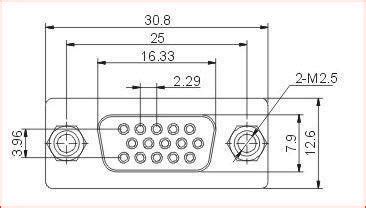
VGA Connector Pinout Diagram
To understand the VGA connector pinout, it’s helpful to have a visual reference. Here is a diagram of the 15-pin VGA connector, with each pin labeled:
| Pin | Signal | Description |
|---|---|---|
| 1 | Red | Red video signal |
| 2 | Green | Green video signal |
| 3 | Blue | Blue video signal |
| 4 | ID2/RES | Monitor ID bit 2, reserved |
| 5 | GND | Ground |
| 6 | Red GND | Red ground |
| 7 | Green GND | Green ground |
| 8 | Blue GND | Blue ground |
| 9 | KEY/PWR | +5V power supply |
| 10 | GND SYNC | Ground for sync signals |
| 11 | ID0/RES | Monitor ID bit 0, reserved |
| 12 | ID1/SDA | Monitor ID bit 1, I2C serial data |
| 13 | Horizontal Sync | Horizontal sync signal |
| 14 | Vertical Sync | Vertical sync signal |
| 15 | ID3/SCL | Monitor ID bit 3, I2C serial clock |

Signal Description
Video Signals (Pins 1, 2, 3)
The VGA connector transmits three analog video signals: red, green, and blue. These signals are carried on pins 1, 2, and 3, respectively. The intensity of each signal determines the brightness of the corresponding color on the display.
Ground Signals (Pins 5, 6, 7, 8, 10)
Several pins on the VGA connector are dedicated to ground signals. Pin 5 is the overall ground, while pins 6, 7, and 8 are ground signals for the red, green, and blue video signals, respectively. Pin 10 is the ground for the sync signals.
Sync Signals (Pins 13, 14)
The VGA connector transmits two sync signals: horizontal sync and vertical sync. These signals are carried on pins 13 and 14, respectively. The horizontal sync signal tells the display when to start a new line, while the vertical sync signal tells the display when to start a new frame.
Power Supply (Pin 9)
Pin 9 on the VGA connector provides a +5V power supply. This can be used to power small devices, such as a monitor’s on-screen display (OSD) circuitry.
Monitor ID Bits (Pins 4, 11, 12, 15)
The VGA connector includes four pins for monitor ID bits. These bits are used to communicate information about the monitor’s capabilities to the computer. The monitor ID bits are:
- Pin 4: ID2/RES (reserved)
- Pin 11: ID0/RES (reserved)
- Pin 12: ID1/SDA (I2C serial data)
- Pin 15: ID3/SCL (I2C serial clock)
The I2C pins (12 and 15) are used for DDC (Display Data Channel) communication between the computer and the monitor.

VGA Signal Timing
To display an image correctly, the timing of the VGA signals must be precise. The VGA standard specifies the timing of the horizontal and vertical sync signals, as well as the video signals.
Horizontal Timing
The horizontal timing of the VGA signal is controlled by the horizontal sync signal. The time between two horizontal sync pulses is called the horizontal scan time, which is typically around 32 microseconds for a resolution of 640×480 at 60 Hz.
During each horizontal scan, the electron beam in the CRT display draws a single line of the image. The beam starts at the left side of the screen and moves to the right, turning on and off to create the pixels in the line. At the end of the line, the beam turns off and quickly returns to the left side of the screen, ready to start the next line.
Vertical Timing
The vertical timing of the VGA signal is controlled by the vertical sync signal. The time between two vertical sync pulses is called the vertical scan time, which is typically around 16.7 milliseconds for a resolution of 640×480 at 60 Hz.
During each vertical scan, the electron beam draws all the lines of the image, starting at the top of the screen and moving down. At the end of the last line, the beam turns off and quickly returns to the top of the screen, ready to start the next frame.
Video Signal Timing
The timing of the video signals (red, green, and blue) is synchronized with the horizontal and vertical sync signals. During each pixel’s time slot, the intensity of the red, green, and blue signals determines the color and brightness of that pixel on the screen.
VGA Resolution and Refresh Rate
The VGA standard supports a variety of resolutions and refresh rates. The most common resolution is 640×480, but higher resolutions like 800×600 and 1024×768 are also widely supported.
The refresh rate is the number of times per second that the display updates the image. A higher refresh rate results in a smoother, more stable image. The most common refresh rates are 60 Hz, 75 Hz, and 85 Hz.
Here is a table of some common VGA resolutions and their typical refresh rates:
| Resolution | Refresh Rates (Hz) |
|---|---|
| 640×480 | 60, 72, 75, 85 |
| 800×600 | 56, 60, 72, 75, 85 |
| 1024×768 | 60, 70, 75, 85 |
| 1280×1024 | 60, 75, 85 |
| 1600×1200 | 60, 65, 70, 75, 85 |
VGA Cable Quality and Length
The quality and length of the VGA cable can have a significant impact on the video signal quality. Longer cables and lower-quality cables are more susceptible to signal degradation, which can result in image artifacts, color distortion, and loss of sharpness.
For best results, it’s recommended to use high-quality VGA cables that are no longer than necessary. Cable lengths up to 25 feet (7.6 meters) should work well for most applications, but longer runs may require a signal booster or a higher-quality cable.
Troubleshooting VGA Connections
If you’re having problems with a VGA connection, there are several things you can check:
- Make sure the cable is securely connected at both ends.
- Check the cable for any visible damage or bent pins.
- Try a different cable to rule out a faulty cable.
- Make sure the monitor is set to the correct input (VGA).
- Check the computer’s video settings to ensure the correct resolution and refresh rate are selected.
- Update the computer’s video drivers to the latest version.
VGA to HDMI Adapters
With the widespread adoption of HDMI in modern displays, you may need to convert a VGA signal to HDMI. This can be done using a VGA to HDMI adapter, which typically includes a small box with a VGA input and an HDMI output.
It’s important to note that these adapters only convert the video signal, not the audio. If you need to transmit audio, you’ll need to use a separate audio cable or a more advanced adapter that includes audio support.
Frequently Asked Questions (FAQ)
What is the maximum resolution supported by VGA?
The maximum resolution supported by VGA depends on the specific hardware, but most VGA systems can support resolutions up to 1920×1440 at 60 Hz.
Can I use a VGA cable for a DVI connection?
No, VGA and DVI are different standards and use different connectors. However, there are adapters available that can convert a VGA signal to DVI or vice versa.
How do I know if my monitor supports VGA?
Most monitors have a label on the back that lists the supported input types. Look for a 15-pin D-sub connector labeled “VGA” or “RGB.”
Can I use a VGA splitter to connect multiple monitors?
Yes, a VGA splitter can be used to send the same video signal to multiple monitors. However, the resolution and refresh rate will be limited to the capabilities of the lowest-spec monitor.
What’s the difference between VGA and SVGA?
SVGA (Super VGA) is an extension of the VGA standard that supports higher resolutions and color depths. While VGA is limited to 640×480 resolution with 16 colors, SVGA can support resolutions up to 1280×1024 with 16.7 million colors.
Conclusion
Understanding the VGA connector pinout and signal timings is essential for anyone working with computer video hardware. While VGA has largely been replaced by newer standards like DVI, HDMI, and DisplayPort, it remains an important legacy standard that is still widely used in many applications.
By knowing the basics of VGA signals and troubleshooting common problems, you can ensure that your VGA connections are working properly and delivering the best possible video quality.
No responses yet