Introduction to Snubber Circuits
In the realm of electrical and electronic systems, protecting sensitive components from power surges and transient voltages is of utmost importance. One such protective measure is the implementation of a snubber circuit. A snubber circuit, also known as a suppressor circuit, is designed to absorb and dissipate excess energy that may otherwise cause damage to components or disrupt the normal operation of a system.
What is a Power Surge?
A power surge, also referred to as a transient voltage, is a brief but intense increase in voltage that exceeds the normal operating range of an electrical system. These surges can be caused by various factors, including:
- Lightning strikes
- Switching of heavy electrical loads
- Faults in power transmission lines
- Electrostatic discharge (ESD)
Power surges can have detrimental effects on electronic components, leading to permanent damage, reduced lifespan, or complete failure. This is where snubber circuits come into play, providing a vital layer of protection against these harmful surges.
How Snubber Circuits Work
A snubber circuit typically consists of a combination of passive components, such as resistors, capacitors, and sometimes inductors. These components are arranged in a specific configuration to absorb and dissipate the excess energy associated with power surges.
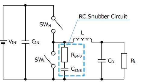
RC Snubber Circuit
One of the most common types of snubber circuits is the RC (Resistor-Capacitor) snubber. In an RC snubber, a resistor and a capacitor are connected in series across the terminals of the component being protected. When a power surge occurs, the capacitor quickly charges up, absorbing the excess energy. The resistor then dissipates this stored energy as heat, preventing it from reaching the protected component.
The values of the resistor and capacitor in an RC snubber are carefully selected based on factors such as the expected surge voltage, the desired suppression level, and the characteristics of the protected component. The time constant of the RC network, determined by the product of the resistance and capacitance, plays a crucial role in the effectiveness of the snubber.
RCD Snubber Circuit
Another variation of the snubber circuit is the RCD (Resistor-Capacitor-Diode) snubber. In addition to the resistor and capacitor, an RCD snubber includes a diode connected in parallel with the resistor. The diode provides a low-impedance path for the capacitor to discharge quickly when the surge voltage subsides.
The presence of the diode in an RCD snubber allows for faster dissipation of the stored energy, reducing the stress on the protected component. However, the selection of the diode is critical, as it must have a sufficient voltage rating and fast recovery characteristics to handle the surge current effectively.
Snubber Circuit Design Considerations
When designing a snubber circuit, several key factors must be taken into account to ensure optimal performance and protection. These include:
-
Surge Voltage and Current: The expected magnitude and duration of the power surges must be considered to determine the appropriate values for the snubber components.
-
Component Ratings: The resistor, capacitor, and diode (if used) must have voltage and current ratings that exceed the maximum expected surge levels. This ensures that the snubber components themselves can withstand the surge energy without failing.
-
Frequency Response: The snubber circuit should be designed to effectively suppress surges across the relevant frequency range. This may require the use of multiple snubber stages or the inclusion of inductors to achieve the desired frequency response.
-
Thermal Management: The resistor in the snubber circuit dissipates the absorbed energy as heat. Proper thermal management, such as heat sinking or adequate ventilation, is necessary to prevent overheating and ensure long-term reliability.
-
System Integration: The snubber circuit must be properly integrated into the overall electrical system, considering factors such as component placement, wiring, and grounding. Improper integration can compromise the effectiveness of the snubber and potentially introduce new vulnerabilities.

Applications of Snubber Circuits
Snubber circuits find applications in a wide range of electrical and electronic systems where power surges pose a threat to sensitive components. Some common applications include:
Power Electronics
In power electronic converters, such as switched-mode power supplies (SMPS) and motor drives, snubber circuits are used to protect semiconductor devices like MOSFETs and IGBTs from voltage spikes during switching transitions. These spikes can occur due to the fast switching speeds and the presence of inductive loads.
Snubber circuits in power electronics help to reduce switching losses, limit voltage overshoots, and prevent device failure. They are particularly important in high-power and high-frequency applications where the energy levels and switching speeds are significant.
Relay and Contactor Protection
Relays and contactors are commonly used for switching electrical loads in various control systems. When these devices open or close, the sudden change in current can generate voltage spikes across the contacts. These spikes can cause arcing, leading to contact erosion and reduced lifespan of the switching devices.
Snubber circuits, often in the form of RC networks, are used across relay and contactor contacts to suppress these voltage spikes. By absorbing the energy associated with the spikes, snubber circuits help to extend the life of the contacts and improve the overall reliability of the switching system.
Inductive Load Switching
Inductive loads, such as transformers, solenoids, and motors, store energy in their magnetic fields. When these loads are switched off, the collapsing magnetic field induces a high-voltage spike across the switching device. This voltage spike can be several times higher than the normal operating voltage and can cause damage to the switching components.
Snubber circuits are employed to absorb the energy stored in the inductive load and limit the voltage spike to a safe level. The snubber network, typically an RC or RCD configuration, is connected across the inductive load to provide a path for the current to flow during the switching transition.
Electromagnetic Interference (EMI) Suppression
Snubber circuits can also play a role in reducing electromagnetic interference (EMI) generated by electrical systems. Fast switching transitions and high-frequency content in power converters and digital circuits can produce unwanted electromagnetic emissions that can interfere with nearby electronic devices.
By incorporating snubber circuits at strategic locations, such as across switching devices or on power supply lines, the high-frequency content of the signals can be attenuated. This helps to mitigate EMI and ensure compliance with electromagnetic compatibility (EMC) regulations.

Snubber Circuit Design Examples
To better understand the practical implementation of snubber circuits, let’s consider a few design examples.
Example 1: RC Snubber for a Power MOSFET
In a switched-mode power supply, a power MOSFET is used as the main switching device. To protect the MOSFET from voltage spikes during turn-off, an RC snubber circuit is employed.
Given:
– MOSFET voltage rating: 200 V
– Maximum expected surge voltage: 250 V
– Desired surge suppression level: 180 V
– Switching frequency: 100 kHz
Step 1: Determine the snubber capacitance.
The snubber capacitance (C) can be calculated based on the expected surge energy and the desired suppression level.
C = (2 × Surge Energy) / (V_max^2 – V_suppression^2)
Assuming a surge energy of 100 µJ:
C = (2 × 100 µJ) / (250 V^2 – 180 V^2) = 3.3 nF
Step 2: Determine the snubber resistance.
The snubber resistance (R) should be chosen to provide critical damping and limit the peak current through the capacitor.
R = sqrt(L / C)
Assuming a stray inductance (L) of 100 nH:
R = sqrt(100 nH / 3.3 nF) = 5.5 Ω
Step 3: Select appropriate component ratings.
– Capacitor: Use a capacitor with a voltage rating higher than the maximum expected surge voltage. In this case, a 400 V ceramic capacitor would be suitable.
– Resistor: Choose a resistor with a power rating sufficient to handle the dissipated energy. The peak power can be estimated as:
P_peak = (V_max^2) / R = (250 V^2) / 5.5 Ω ≈ 11.4 kW
A high-pulse-energy resistor, such as a thick-film or wire-wound type, with a power rating of at least 20 W would be appropriate.
Example 2: RCD Snubber for a Relay Contact
In a control system, a relay is used to switch an inductive load. To protect the relay contacts from voltage spikes during turn-off, an RCD snubber circuit is implemented.
Given:
– Relay contact voltage rating: 250 V
– Inductive load: 100 mH
– Maximum expected surge current: 5 A
Step 1: Determine the snubber capacitance.
The snubber capacitance (C) can be calculated based on the maximum expected surge current and the desired voltage suppression level. Assuming a suppression level of 200 V:
C = (Surge Current × Inductance) / Voltage Suppression
C = (5 A × 100 mH) / 200 V = 2.5 µF
Step 2: Determine the snubber resistance.
The snubber resistance (R) should be chosen to provide adequate damping and limit the peak capacitor current.
R = Voltage Suppression / Surge Current
R = 200 V / 5 A = 40 Ω
Step 3: Select the snubber diode.
The snubber diode should have a voltage rating higher than the maximum expected surge voltage and a fast recovery time to minimize losses. A fast recovery diode with a voltage rating of 400 V and a current rating of at least 5 A would be suitable.
Step 4: Select appropriate component ratings.
– Capacitor: Use a capacitor with a voltage rating higher than the voltage suppression level. In this case, a 250 V polypropylene capacitor would be appropriate.
– Resistor: Choose a resistor with a power rating sufficient to handle the dissipated energy. The average power can be estimated as:
P_avg = (Surge Current^2 × R) / 2
P_avg = (5 A^2 × 40 Ω) / 2 = 500 W
A high-power wire-wound resistor with a rating of at least 500 W would be suitable.
These examples demonstrate the process of designing snubber circuits for specific applications. The actual component values and ratings may vary depending on the specific requirements and constraints of each system.

Frequently Asked Questions (FAQ)
-
What is the purpose of a snubber circuit?
A snubber circuit is designed to protect sensitive electronic components from power surges and transient voltages. It absorbs and dissipates the excess energy associated with these surges, preventing damage to the protected components. -
What are the common types of snubber circuits?
The two common types of snubber circuits are: - RC (Resistor-Capacitor) snubber: Consists of a resistor and a capacitor connected in series across the protected component.
-
RCD (Resistor-Capacitor-Diode) snubber: Includes a resistor, a capacitor, and a diode connected in a specific configuration to provide improved surge suppression and faster energy dissipation.
-
How do I select the values for the components in a snubber circuit?
The selection of component values in a snubber circuit depends on factors such as the expected surge voltage and current, desired suppression level, and the characteristics of the protected component. The resistor and capacitor values are chosen to provide effective surge suppression while considering the power dissipation and thermal management requirements. -
Can a snubber circuit be used for EMI suppression?
Yes, snubber circuits can be used to reduce electromagnetic interference (EMI) generated by electrical systems. By attenuating high-frequency content in switching transitions and power supply lines, snubber circuits can help mitigate EMI and ensure compliance with electromagnetic compatibility (EMC) regulations. -
Are there any limitations or drawbacks to using snubber circuits?
While snubber circuits provide effective protection against power surges, they do have some limitations and drawbacks: - Snubber circuits add additional components to the system, increasing complexity and cost.
- The resistor in the snubber circuit dissipates energy as heat, which may require proper thermal management.
- Improperly designed or integrated snubber circuits can introduce new vulnerabilities or compromise the overall system performance.
- Snubber circuits are not a complete substitute for other protective measures, such as fuses, circuit breakers, or transient voltage suppressors (TVS).
Conclusion
Snubber circuits play a vital role in protecting sensitive electronic components from the damaging effects of power surges and transient voltages. By absorbing and dissipating excess energy, snubber circuits help to extend the lifespan of components, improve system reliability, and prevent costly failures.
Understanding the principles behind snubber circuits and their various configurations, such as RC and RCD snubbers, is crucial for effective implementation. Proper design considerations, including component selection, ratings, and system integration, ensure optimal performance and protection.
Snubber circuits find applications across a wide range of electrical and electronic systems, from power electronics and relay protection to inductive load switching and EMI suppression. As technology advances and the demand for reliable and robust systems grows, the importance of snubber circuits in safeguarding against power surges will only continue to increase.
By incorporating well-designed snubber circuits into their systems, engineers and designers can enhance the resilience and longevity of electronic devices, ultimately contributing to more reliable and efficient solutions in various domains.
No responses yet