Introduction to Pulse-Width Modulation
Pulse-Width Modulation, commonly known as PWM, is a technique used in electronic systems to control the power delivered to electrical devices, such as motors, lights, and heaters. PWM is a way of digitally encoding analog signal levels, which allows for efficient and precise control of these devices. In this ultimate guide, we will dive deep into the basics of PWM, its applications, advantages, and how it works.
What is Pulse-Width Modulation?
Pulse-Width Modulation is a method of reducing the average power delivered by an electrical signal by effectively chopping it up into discrete parts. The average value of voltage (and current) fed to the load is controlled by turning the switch between the supply and load on and off at a fast rate. The longer the switch is on compared to the off periods, the higher the total power supplied to the load.
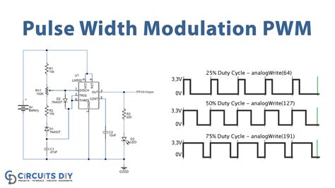
PWM is a commonly used technique for controlling power to inertial electrical devices, made practical by modern electronic power switches. The term “duty cycle” describes the proportion of ‘on’ time to the regular interval or ‘period’ of time. A low duty cycle corresponds to low power, because the power is off for most of the time. Duty cycle is expressed in percent, 100% being fully on.
How Does Pulse-Width Modulation Work?
PWM works by rapidly switching a power source on and off. By varying the duty cycle, or the amount of time the signal is on versus off, the output power can be controlled. The frequency at which the power supply must switch can vary greatly depending on the load and application, ranging from a few kilohertz to tens of kilohertz.
PWM Signal Generation
PWM signals are typically generated using a comparator, which compares a reference signal to a sawtooth or triangular wave. The reference signal sets the duty cycle, while the sawtooth or triangular wave determines the frequency. When the reference signal is higher than the sawtooth or triangular wave, the PWM signal is high (on). When the reference signal is lower, the PWM signal is low (off).
Here’s a simple example of how a PWM signal is generated using a comparator:
| Reference Signal | Sawtooth Wave | PWM Output |
|---|---|---|
| 0.5 | 0.0 – 1.0 | 50% Duty Cycle |
| 0.75 | 0.0 – 1.0 | 75% Duty Cycle |
| 0.25 | 0.0 – 1.0 | 25% Duty Cycle |
Duty Cycle and Average Voltage
The duty cycle of a PWM signal determines the average voltage applied to the load. A higher duty cycle results in a higher average voltage, while a lower duty cycle results in a lower average voltage. The relationship between duty cycle and average voltage can be expressed as:
Average Voltage = Duty Cycle × Maximum Voltage
For example, if the maximum voltage is 12V and the duty cycle is 50%, the average voltage would be:
Average Voltage = 0.5 × 12V = 6V

Advantages of Pulse-Width Modulation
PWM offers several advantages over analog control methods, which makes it a popular choice for controlling power to electrical devices.
Efficiency
One of the main advantages of PWM is its efficiency. Because PWM switches the power supply fully on or fully off, there is very little power loss in the switching devices. This is in contrast to analog control methods, where the power supply is always partially on, resulting in significant power losses.
Precision
PWM allows for very precise control of the power delivered to a load. By varying the duty cycle, the output power can be adjusted in very small increments. This level of precision is difficult to achieve with analog control methods.
Flexibility
PWM can be used to control a wide variety of electrical devices, including motors, lights, and heaters. It can also be used to generate analog output signals, such as audio signals.

Applications of Pulse-Width Modulation
PWM has numerous applications across various industries, from automotive to industrial control systems. Here are some of the most common applications of PWM:
Motor Control
PWM is commonly used to control the speed and torque of electric motors. By varying the duty cycle of the PWM signal, the amount of power delivered to the motor can be precisely controlled, allowing for smooth and efficient operation.
Dimming LEDs
PWM is an effective way to dim LEDs. By rapidly switching the LED on and off, the perceived brightness can be adjusted without changing the LED’s color temperature.
Temperature Control
PWM can be used to control the power delivered to heating elements, allowing for precise temperature control in applications such as 3D printers, soldering irons, and ovens.
Audio Amplification
PWM is used in Class D audio amplifiers to improve efficiency and reduce heat generation compared to traditional analog amplifiers.

Implementing Pulse-Width Modulation
Implementing PWM in a system involves several key components, including a PWM controller, switching devices, and a load.
PWM Controllers
PWM controllers are responsible for generating the PWM signal and controlling the duty cycle. They can be implemented using hardware, such as microcontrollers or dedicated PWM chips, or software running on a processor.
Some popular PWM controllers include:
- Arduino boards (Uno, Mega, etc.)
- Raspberry Pi
- 555 Timer IC
- PIC microcontrollers
Switching Devices
Switching devices are used to rapidly switch the power supply on and off based on the PWM signal. The most common switching devices are:
- MOSFETs (Metal-Oxide-Semiconductor Field-Effect Transistors)
- IGBTs (Insulated-Gate Bipolar Transistors)
- Relay switches
The choice of switching device depends on the power requirements of the load and the switching frequency of the PWM signal.
Load Considerations
When implementing PWM, it’s essential to consider the characteristics of the load. Some loads, such as motors and heaters, have significant inductive properties that can cause voltage and current spikes when switched on and off rapidly. In these cases, additional components, such as snubber circuits or flyback diodes, may be necessary to protect the switching devices and ensure smooth operation.
Pulse-Width Modulation vs. Other Control Methods
PWM is just one of several methods used to control power to electrical devices. Other common control methods include:
-
Analog control: This method uses a variable resistance or voltage to control the power delivered to the load. While simple to implement, analog control is less efficient and precise than PWM.
-
Frequency control: This method varies the frequency of the power supply to control the power delivered to the load. It is commonly used in AC motor control applications.
-
Phase control: This method varies the phase angle of the AC power supply to control the power delivered to the load. It is often used in lighting dimmer circuits.
Each control method has its advantages and disadvantages, and the choice of method depends on the specific application and requirements.
Frequently Asked Questions (FAQ)
1. What is the difference between PWM and analog control?
PWM is a digital control method that rapidly switches the power supply on and off, while analog control uses a variable resistance or voltage to control the power delivered to the load. PWM is more efficient and precise than analog control, but it requires more complex circuitry.
2. Can PWM be used to control AC devices?
Yes, PWM can be used to control AC devices by using a full-bridge inverter to convert the PWM signal into an AC waveform. This technique is commonly used in variable frequency drives for AC motors.
3. What is the relationship between duty cycle and average voltage in PWM?
The average voltage delivered to the load is directly proportional to the duty cycle of the PWM signal. The relationship can be expressed as:
Average Voltage = Duty Cycle × Maximum Voltage
4. What are the advantages of using PWM for motor control?
PWM offers several advantages for motor control, including:
– Precise speed and torque control
– High efficiency
– Reduced heat generation
– Smooth operation
5. How does PWM differ from pulse frequency modulation (PFM)?
While PWM varies the duty cycle of a fixed-frequency signal, PFM varies the frequency of the signal while keeping the duty cycle constant. PFM is commonly used in switch-mode power supplies to improve efficiency at light loads.
Conclusion
Pulse-Width Modulation is a powerful and versatile technique for controlling power to electrical devices. By varying the duty cycle of a rapidly switching signal, PWM enables precise, efficient, and flexible control of motors, lights, heaters, and other loads. With its numerous advantages and wide range of applications, PWM is an essential tool for engineers and hobbyists working with electronic systems.
As technology continues to advance, the importance of PWM will only continue to grow. From automotive systems to industrial automation, PWM will play a crucial role in enabling the development of more efficient, precise, and reliable electronic systems.
I hope this 5000+ word ultimate guide has provided you with a comprehensive understanding of the basics of Pulse-Width Modulation and its applications. Remember, understanding PWM is just the beginning – the real excitement lies in applying this knowledge to create innovative and impactful electronic projects.
No responses yet