Introduction to Flex Sensors
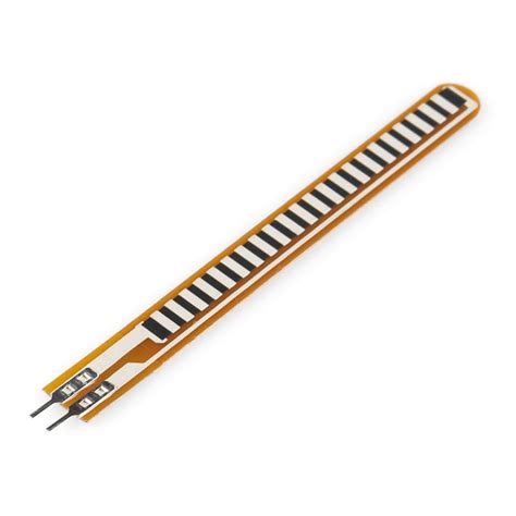
Flex sensors, also known as bend sensors, are a type of variable resistor that change resistance when bent or flexed. They are commonly used in various applications such as wearable devices, robotics, gaming controllers, and more. Flex sensors allow you to measure the amount of bending or flexing applied to them, enabling the development of interactive and responsive projects.
In this article, we will explore the working principle of flex sensors and provide a step-by-step guide on how to interface a flex sensor with an Arduino board. We will also discuss the various applications of flex sensors and provide code examples to help you get started with your own flex sensor projects.
How Flex Sensors Work
Flex sensors are based on the principle of resistive sensing. They are composed of a thin, flexible substrate coated with a layer of conductive material, typically carbon or polymer ink. When the sensor is straight, the conductive particles are evenly distributed, resulting in a specific resistance value. However, when the sensor is bent or flexed, the conductive particles move apart, increasing the resistance of the sensor.
The resistance of a flex sensor varies depending on the amount of bending applied to it. The more the sensor is bent, the higher the resistance becomes. Conversely, when the sensor is straightened back to its original position, the resistance decreases. This change in resistance can be measured and used to determine the degree of bending or flexing.
Flex sensors come in various sizes and shapes, with different resistance ranges. The most common types of flex sensors have a resistance range of about 10kΩ to 50kΩ when straight and can go up to 100kΩ or more when fully bent. The specific resistance range may vary depending on the manufacturer and model of the flex sensor.

Interfacing Flex Sensor with Arduino
To interface a flex sensor with an Arduino board, you will need the following components:
- Arduino board (e.g., Arduino Uno)
- Flex sensor
- 10kΩ resistor
- Breadboard
- Jumper wires
Circuit Diagram
Here’s a simple circuit diagram illustrating how to connect a flex sensor to an Arduino:
+5V
  |
  |
  |
 10kΩ
  |
  |
  |
Flex Sensor
  |
  |
  |
 GND
Step-by-Step Guide
- Connect one end of the flex sensor to the 5V pin of the Arduino.
- Connect the other end of the flex sensor to a 10kΩ resistor.
- Connect the other end of the 10kΩ resistor to ground (GND).
- Connect the point between the flex sensor and the 10kΩ resistor to an analog input pin of the Arduino (e.g., A0).
The 10kΩ resistor acts as a voltage divider, allowing you to measure the change in voltage across the flex sensor as its resistance changes.
Arduino Code
Here’s a simple Arduino sketch that reads the analog value from the flex sensor and prints it to the serial monitor:
const int flexPin = A0;

void setup() {
  Serial.begin(9600);
}

void loop() {
  int flexValue = analogRead(flexPin);
  Serial.println(flexValue);
  delay(100);
}
In this code:
– The flexPin variable is set to A0, representing the analog input pin connected to the flex sensor.
– In the setup() function, Serial.begin(9600) initializes serial communication at a baud rate of 9600.
– In the loop() function, analogRead(flexPin) reads the analog value from the flex sensor and stores it in the flexValue variable.
– The flexValue is then printed to the serial monitor using Serial.println(flexValue).
– A delay of 100 milliseconds is added to provide a small pause between readings.
Upload this sketch to your Arduino board, open the serial monitor, and observe the values printed as you bend and flex the sensor.

Calibration and Mapping
To make the flex sensor readings more meaningful and usable in your projects, you may need to calibrate and map the sensor values to a specific range. Calibration involves determining the minimum and maximum resistance values of the flex sensor when it is straight and fully bent. These values can then be used to map the sensor readings to a desired range, such as 0 to 180 degrees or 0 to 100 percent.
Here’s an example of how you can calibrate and map the flex sensor readings:
- Determine the minimum and maximum resistance values:
- Straighten the flex sensor and note down the analog reading. This will be the minimum value.
-
Fully bend the flex sensor and note down the analog reading. This will be the maximum value.
-
Modify the Arduino code to map the sensor readings:
const int flexPin = A0;
const int minFlexValue = 200; // Minimum value when straight
const int maxFlexValue = 900; // Maximum value when fully bent

void setup() {
  Serial.begin(9600);
}

void loop() {
  int flexValue = analogRead(flexPin);
  int mappedValue = map(flexValue, minFlexValue, maxFlexValue, 0, 100);
  Serial.println(mappedValue);
  delay(100);
}
In this modified code:
– The minFlexValue and maxFlexValue variables are set to the minimum and maximum analog readings obtained during calibration.
– The map() function is used to map the flexValue from the range of minFlexValue to maxFlexValue to a desired range of 0 to 100.
– The mappedValue is then printed to the serial monitor.
Adjust the minFlexValue and maxFlexValue according to your specific flex sensor and calibration results.

Applications of Flex Sensors
Flex sensors find applications in various fields, enabling the development of interactive and responsive projects. Here are a few examples:
- Wearable Devices:
- Flex sensors can be integrated into gloves, clothing, or wearable accessories to detect and measure hand gestures, body movements, or joint angles.
-
This enables the development of gesture-based control systems, virtual reality interactions, or monitoring of physical therapy progress.
-
Robotics:
- Flex sensors can be used in robotic arms, grippers, or fingers to provide feedback on the bending and flexing of mechanical joints.
-
By measuring the flex sensor readings, robots can perform precise grasping, manipulation, or gesture recognition tasks.
-
Gaming Controllers:
- Flex sensors can be incorporated into gaming controllers to enhance the gaming experience and provide more intuitive and immersive controls.
-
For example, a flex sensor can be used to detect the bending of a finger to trigger actions like firing a weapon or controlling the throttle in a racing game.
-
Music and Art:
- Flex sensors can be used to create interactive musical instruments or art installations.
-
By mapping the flex sensor readings to different parameters such as pitch, volume, or visual effects, artists can create unique and expressive performances.
-
Automotive:
- Flex sensors can be employed in automotive applications to detect the position or movement of various components.
- For instance, flex sensors can be used to detect the position of pedals, steering wheel angle, or seat adjustments for personalized settings or safety features.
These are just a few examples, and the possibilities are endless. Flex sensors provide a simple and effective way to add interactivity and responsiveness to your projects, enabling you to create innovative and engaging applications.
Frequently Asked Questions (FAQ)
- What is the typical resistance range of a flex sensor?
-
The typical resistance range of a flex sensor varies depending on the manufacturer and model. However, most flex sensors have a resistance range of about 10kΩ to 50kΩ when straight and can go up to 100kΩ or more when fully bent.
-
Can I use a flex sensor with other microcontrollers besides Arduino?
-
Yes, you can use a flex sensor with other microcontrollers such as Raspberry Pi, ESP32, or any microcontroller that has analog input capabilities. The interfacing process may differ slightly based on the specific microcontroller and its programming language.
-
How do I determine the minimum and maximum resistance values of my flex sensor?
-
To determine the minimum and maximum resistance values, you need to calibrate your flex sensor. Straighten the sensor and note down the analog reading as the minimum value. Then, fully bend the sensor and note down the analog reading as the maximum value. These values can be used for mapping the sensor readings to a desired range.
-
Can I use multiple flex sensors with a single Arduino board?
-
Yes, you can connect multiple flex sensors to a single Arduino board. Each flex sensor will require its own analog input pin and a separate voltage divider circuit. Make sure your Arduino board has enough analog input pins to accommodate all the flex sensors you want to use.
-
How durable are flex sensors, and what is their lifespan?
- The durability and lifespan of flex sensors depend on various factors such as the quality of the sensor, the materials used, and the environmental conditions. Flex sensors are designed to withstand repeated bending and flexing, but excessive strain or improper handling can lead to damage. With proper care and usage, flex sensors can last for a considerable amount of time. However, it’s always a good idea to refer to the manufacturer’s specifications and guidelines for specific information on the sensor’s durability and expected lifespan.
Conclusion
Flex sensors provide a simple and effective way to add bending and flexing detection capabilities to your projects. By understanding the working principle of flex sensors and how to interface them with an Arduino board, you can create interactive and responsive applications in various fields such as wearable devices, robotics, gaming, and more.
In this article, we explored the fundamentals of flex sensors, including their construction and resistance characteristics. We provided a step-by-step guide on how to connect a flex sensor to an Arduino board and read the analog values using a simple voltage divider circuit. We also discussed calibration and mapping techniques to make the sensor readings more meaningful and usable.
Furthermore, we highlighted some exciting applications of flex sensors, showcasing their versatility and potential in different domains. Whether you’re developing a gesture-controlled device, a robotic arm, or an interactive art installation, flex sensors can add a new dimension of interactivity and responsiveness to your projects.
As you embark on your flex sensor projects, remember to experiment, explore, and have fun. The possibilities are endless, and with the knowledge and techniques provided in this article, you’re well-equipped to create innovative and engaging applications using flex sensors and Arduino.
Happy flexing and coding!
No responses yet