Introduction to Rigid-Flex PCBs
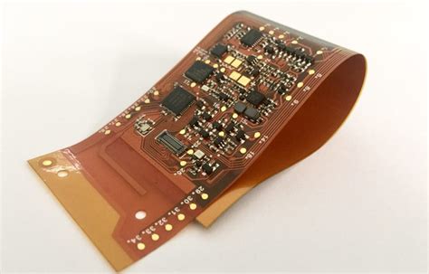
Rigid-flex PCBs are a unique type of printed circuit board that combines the best features of rigid and flexible circuits. These boards consist of multiple layers of Flexible PCB substrate interspersed with rigid PCB sections. This innovative design allows the final product to be bent and folded to fit into tight spaces and unique enclosures.
Rigid-flex PCBs offer numerous advantages over traditional rigid PCBs, including:
- Reduced weight and space requirements
- Increased reliability and durability
- Improved electrical performance
- Enhanced design flexibility
- Streamlined assembly process
Applications of Rigid-Flex PCBs
Rigid-flex PCBs find applications in various industries where space constraints, reliability, and performance are critical factors. Some common applications include:
- Aerospace and defense
- Medical devices
- Automotive electronics
- Consumer electronics
- Industrial automation
- Telecommunications
Rigid-Flex PCB Manufacturing Process
The manufacturing process for rigid-flex PCBs is more complex than that of standard rigid PCBs due to the combination of flexible and rigid materials. Here’s an overview of the key steps involved:
1. Design and Preparation
The first step in the manufacturing process is to design the rigid-flex PCB using specialized CAD software. The design must take into account the specific requirements of the application, such as the number of layers, the placement of rigid and flexible sections, and the desired bend radius.
Once the design is finalized, the manufacturer prepares the necessary materials, including the flexible PCB substrate, rigid PCB laminates, and adhesives.
2. Lamination
The flexible PCB substrate is laminated with the rigid PCB laminates using a combination of heat and pressure. The adhesives used in this process must be carefully selected to ensure proper bonding between the layers and to maintain the flexibility of the circuit.
3. Drilling and Plating
After lamination, the rigid-flex PCB undergoes drilling and plating processes to create the necessary vias and interconnects between the layers. This step requires precise control to ensure that the holes are drilled accurately and the plating is uniform.
4. Etching and Masking
The next step is to etch the copper traces onto the PCB using a photolithographic process. This involves applying a photoresist mask to the copper layer, exposing it to UV light, and then etching away the unwanted copper.
5. Solder Mask Application
A solder mask is applied to the PCB to protect the copper traces from oxidation and to prevent solder bridging during the assembly process. The solder mask also provides insulation between the traces.
6. Surface Finish
The final step in the manufacturing process is to apply a surface finish to the exposed copper pads. This can be done using various methods, such as HASL (Hot Air Solder Leveling), ENIG (Electroless Nickel Immersion Gold), or OSP (Organic Solderability Preservative).

Considerations for Rigid-Flex PCB Design
Designing a rigid-flex PCB requires careful consideration of several factors to ensure optimal performance and reliability. Here are some key points to keep in mind:
Bend Radius
The bend radius is a critical parameter in rigid-flex PCB design, as it determines the minimum distance the board can be bent without causing damage to the copper traces or the flexible substrate. The bend radius is typically specified by the manufacturer and must be adhered to during the design process.
Layer Stack-Up
The layer stack-up of a rigid-flex PCB is another important consideration. The number of layers and the arrangement of rigid and flexible sections will depend on the specific requirements of the application. In general, rigid-flex PCBs can have anywhere from 2 to 30 layers, with the flexible layers typically placed in the center of the stack-up.
Here’s an example of a 6-layer rigid-flex PCB Stack-Up:
| Layer | Material |
|---|---|
| Top Cover | Polyimide |
| Top Copper | Copper |
| Flexible Core | Polyimide |
| Bottom Copper | Copper |
| Rigid Core | FR-4 |
| Bottom Cover | Polyimide |
Material Selection
The choice of materials for a rigid-flex PCB is critical to its performance and reliability. The flexible substrate is typically made from polyimide, which offers excellent thermal and mechanical properties. The rigid sections are usually made from FR-4, a glass-reinforced epoxy laminate.
When selecting materials, it’s important to consider factors such as the operating temperature range, the required flexibility, and the electrical properties of the material.
Trace Width and Spacing
The width and spacing of the copper traces on a rigid-flex PCB must be carefully designed to ensure proper signal integrity and to prevent crosstalk between adjacent traces. The minimum trace width and spacing will depend on the manufacturing capabilities of the PCB fabricator and the specific requirements of the application.
Shielding and Grounding
Proper shielding and grounding are essential for ensuring the electrical performance and reliability of a rigid-flex PCB. The design must incorporate appropriate shielding measures, such as ground planes and via stitching, to minimize electromagnetic interference (EMI) and to provide a low-impedance path for return currents.

Advantages of Working with an Experienced Rigid-Flex PCB Manufacturer
Partnering with an experienced rigid-flex PCB manufacturer can offer numerous benefits, including:
-
Design Support: An experienced manufacturer can provide valuable guidance and support throughout the design process, helping to optimize the PCB layout for manufacturing and ensuring that the design meets all necessary requirements.
-
Advanced Manufacturing Capabilities: A reputable rigid-flex PCB manufacturer will have access to state-of-the-art manufacturing equipment and processes, enabling them to produce high-quality boards with tight tolerances and advanced features.
-
Quality Control: Experienced manufacturers employ rigorous quality control measures to ensure that each PCB meets the highest standards of reliability and performance. This includes automated optical inspection (AOI), X-ray inspection, and electrical testing.
-
Quick Turnaround Times: With streamlined manufacturing processes and efficient supply chain management, an experienced rigid-flex PCB manufacturer can offer fast turnaround times, helping to reduce time-to-market for new products.
-
Cost Savings: By working with a manufacturer that has experience in rigid-flex PCB production, companies can often achieve significant cost savings through optimized designs, reduced material waste, and economies of scale.

FAQ
1. What is the minimum bend radius for a rigid-flex PCB?
The minimum bend radius for a rigid-flex PCB depends on several factors, including the thickness of the flexible substrate, the number of layers, and the copper weight. As a general rule, the minimum bend radius is typically 6-10 times the thickness of the flexible material. However, it’s always best to consult with your PCB manufacturer for specific recommendations.
2. Can rigid-flex PCBs be used in high-temperature applications?
Yes, rigid-flex PCBs can be designed to withstand high temperatures by selecting appropriate materials and manufacturing processes. Polyimide, the most common flexible substrate material, has a Glass Transition Temperature (Tg) of around 260°C, making it suitable for many high-temperature applications.
3. How do I choose the right layer stack-up for my rigid-flex PCB?
The choice of layer stack-up for a rigid-flex PCB depends on the specific requirements of your application, such as the number of components, the required signal integrity, and the mechanical constraints. It’s best to work closely with your PCB manufacturer to determine the optimal layer stack-up for your design.
4. What is the maximum number of layers possible in a rigid-flex PCB?
Rigid-flex PCBs can be manufactured with up to 30 layers or more, depending on the capabilities of the PCB fabricator. However, as the number of layers increases, so does the complexity of the manufacturing process and the associated costs. Most applications can be accommodated with a layer count in the range of 6-12 layers.
5. How do I ensure the reliability of my rigid-flex PCB?
To ensure the reliability of your rigid-flex PCB, it’s important to work with an experienced manufacturer that follows best practices in design, material selection, and manufacturing. This includes using appropriate materials, adhering to design guidelines for bend radius and trace width/spacing, and implementing robust quality control measures throughout the production process.
Conclusion
Rigid-flex PCBs offer a unique combination of flexibility and durability, making them an ideal choice for applications that require high reliability in compact spaces. By understanding the key considerations in rigid-flex PCB design and manufacturing, and by partnering with an experienced PCB manufacturer, companies can unlock the full potential of this innovative technology.
As the demand for smaller, lighter, and more reliable electronics continues to grow, rigid-flex PCBs will play an increasingly important role in enabling the next generation of products and systems.
No responses yet