What is a Flex PCB?
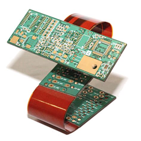
A Flex PCB is a type of printed circuit board that uses flexible materials, such as polyimide or polyester, as its base substrate. Unlike traditional rigid PCBs, Flex PCBs can bend, fold, and twist without damaging the electronic components or the interconnections between them. This flexibility enables designers to create more compact and space-efficient electronic devices, especially in applications where space is limited or where the board needs to conform to a specific shape.
Advantages of Flex PCBs
Flex PCBs offer several advantages over rigid PCBs, including:
- Flexibility: Flex PCBs can bend and fold, allowing for more compact and space-efficient designs.
- Durability: The flexible materials used in Flex PCBs are highly resistant to shock, vibration, and extreme temperatures.
- Lightweight: Flex PCBs are typically thinner and lighter than their rigid counterparts, making them ideal for portable and wearable devices.
- Improved signal integrity: The shorter interconnections in Flex PCBs reduce signal loss and interference, resulting in better overall performance.
- Cost-effective: Flex PCBs can reduce the need for connectors and cables, which can lower the overall cost of the final product.
Flex PCB Manufacturing Process
The manufacturing process for Flex PCBs is similar to that of rigid PCBs, but with a few key differences to accommodate the flexible materials and unique design requirements.
1. Design and Formatting
The first step in Flex PCB manufacturing is designing the board layout using computer-aided design (CAD) software. The designer must consider the specific requirements of the application, such as the number of layers, the type of components, and the desired flexibility. The design files are then formatted and prepared for the manufacturing process.
2. Material Selection
The next step is to select the appropriate flexible substrate material, which is typically polyimide or polyester. The choice of material depends on the specific application requirements, such as the desired flexibility, temperature resistance, and dielectric properties.
3. Lamination
The flexible substrate is then laminated with copper foil on one or both sides, depending on the number of layers required. The lamination process involves applying heat and pressure to bond the copper foil to the substrate material.
4. Drilling and Patterning
After lamination, the Flex PCB undergoes drilling and patterning processes to create the necessary holes and circuit patterns. This is typically done using a combination of mechanical drilling, laser drilling, and photolithography techniques.
5. Etching and Plating
The unwanted copper is then etched away, leaving only the desired circuit patterns on the flexible substrate. The board is then plated with a protective layer, such as gold or nickel, to prevent oxidation and improve conductivity.
6. Solder Mask and Silkscreen
A solder mask is applied to the Flex PCB to protect the copper traces from damage and to prevent short circuits. The silkscreen layer is then added to provide component labels and other markings for assembly and testing.
7. Cutting and Finishing
Finally, the Flex PCB is cut to its final shape and size using a variety of methods, such as die-cutting, laser cutting, or routing. Any necessary additional features, such as stiffeners or adhesives, are added at this stage.

Flex PCB Assembly
Once the Flex PCB has been manufactured, it is ready for assembly. The assembly process involves attaching electronic components to the board and creating the necessary interconnections between them.
Surface Mount Technology (SMT)
Surface Mount Technology (SMT) is the most common method for assembling Flex PCBs. In SMT, electronic components are placed directly onto the surface of the board and soldered in place using a reflow oven. This method is fast, efficient, and well-suited for high-volume production.
Through-Hole Technology (THT)
Through-Hole Technology (THT) is another assembly method that involves inserting component leads through pre-drilled holes in the Flex PCB and soldering them in place. While THT is less common than SMT, it is still used for certain types of components, such as connectors and large transformers.
Flex PCB Assembly Challenges
Assembling Flex PCBs presents some unique challenges compared to rigid PCBs, including:
- Handling: Flex PCBs are more delicate than rigid PCBs and require special handling techniques to prevent damage during assembly.
- Soldering: The flexible nature of Flex PCBs can make soldering more difficult, as the board may move or deform during the process.
- Strain relief: Proper strain relief techniques must be used to prevent damage to the components and interconnections due to repeated flexing of the board.

Flex PCB Layer Stackup
Flex PCBs can be manufactured with a varying number of layers, depending on the complexity and requirements of the application. The most common layer configurations for Flex PCBs are:
| Layers | Description |
|---|---|
| 1 | Single-sided Flex PCB with components on one side |
| 2 | Double-sided Flex PCB with components on both sides |
| 4 | Multi-layer Flex PCB with two signal layers and two power/ground layers |
| 6 | Multi-layer Flex PCB with four signal layers and two power/ground layers |
| 8 | Multi-layer Flex PCB with six signal layers and two power/ground layers |
| 10 | Multi-layer Flex PCB with eight signal layers and two power/ground layers |
As the number of layers increases, so does the complexity and cost of manufacturing. However, multi-layer Flex PCBs offer several advantages, such as increased circuit density, improved signal integrity, and better power distribution.

Applications of Flex PCBs
Flex PCBs are used in a wide range of applications across various industries, including:
- Consumer electronics: Smartphones, tablets, wearables, and other portable devices
- Medical devices: Implantable devices, diagnostic equipment, and patient monitoring systems
- Automotive: In-vehicle infotainment systems, sensors, and engine control units
- Aerospace and defense: Avionics, satellites, and military communication systems
- Industrial automation: Robotics, motion control systems, and sensor networks
Frequently Asked Questions (FAQ)
1. What is the minimum bend radius for a Flex PCB?
The minimum bend radius for a Flex PCB depends on the thickness of the board and the materials used. As a general rule, the minimum bend radius should be at least 6 times the thickness of the board to prevent damage to the copper traces and other components.
2. Can Flex PCBs be used in high-temperature environments?
Yes, Flex PCBs can be designed to withstand high temperatures by using specialized materials, such as polyimide, which can operate in temperatures up to 260°C. However, the specific temperature range will depend on the materials and components used in the board.
3. How do I choose the right number of layers for my Flex PCB?
The number of layers in a Flex PCB depends on the complexity of the circuit, the number of components, and the space constraints of the application. As a general guideline, use the minimum number of layers necessary to achieve the desired functionality and performance while keeping costs and manufacturing complexity in check.
4. Can Flex PCBs be repaired if damaged?
Repairing a damaged Flex PCB can be challenging due to the delicate nature of the flexible materials and the small size of the components. In most cases, it is more cost-effective to replace the entire board rather than attempting to repair it. However, minor repairs, such as replacing a single component or repairing a broken trace, may be possible depending on the extent of the damage.
5. How do I choose the right Flex PCB Manufacturer?
When choosing a Flex PCB manufacturer, consider factors such as their experience, capabilities, quality control processes, and customer support. Look for a manufacturer that has a proven track record of producing high-quality Flex PCBs and can meet your specific requirements in terms of layer count, materials, and assembly options. It is also important to consider their lead times, pricing, and minimum order quantities to ensure they align with your project needs and budget.
Conclusion
Flexible PCB Manufacturing and assembly is a complex process that requires specialized knowledge, materials, and equipment. By understanding the basics of Flex PCB design, manufacturing, and assembly, you can make informed decisions when developing your next electronic product. Whether you need a simple single-layer Flex PCB or a complex multi-layer board, working with an experienced Flex PCB manufacturer can help ensure the success of your project.
No responses yet