Introduction to STM32 Microcontrollers
STM32 is a family of 32-bit microcontroller integrated circuits by STMicroelectronics. These microcontrollers are based on the ARM Cortex-M processor cores and offer a wide range of performance, features, and packages. STM32 microcontrollers are popular for their high performance, low power consumption, and versatility in various applications such as industrial automation, automotive systems, IoT devices, and consumer electronics.
Key Features of STM32 Microcontrollers
- 32-bit ARM Cortex-M processor cores (M0, M0+, M3, M4, M7)
- Wide range of operating frequencies (up to 480 MHz)
- Various memory options (Flash, SRAM, EEPROM)
- Rich set of peripherals (USB, Ethernet, CAN, I2C, SPI, UART, ADC, DAC, etc.)
- Low power consumption modes
- Multiple package options (LQFP, UFQFPN, WLCSP, BGA)
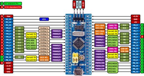
STM32 Pinout Overview
The pinout of an STM32 microcontroller refers to the arrangement and function of the pins on the device package. Understanding the pinout is crucial for designing circuits and interfacing with external components. In this section, we will explore the general structure and nomenclature of STM32 pinouts.
Pin Naming Convention
STM32 pins are typically named using a combination of letters and numbers that indicate their function and location on the package. The naming convention follows the format:
PX[Y]
Where:
– P stands for “Port”
– X is a letter (A, B, C, etc.) representing the port group
– Y is an optional number representing the pin number within the port group
For example, PA0 refers to Pin 0 of Port A, while PB12 refers to Pin 12 of Port B.
Power Supply and Ground Pins
STM32 microcontrollers require a stable power supply and proper grounding for reliable operation. The power supply and ground pins are essential for providing the necessary voltages to the device. Common power supply and ground pins include:
VDD: Main power supply voltage (e.g., 3.3V)VSS: GroundVDDA: Analog power supply voltageVSSA: Analog groundVREF+: Positive reference voltage for analog peripheralsVREF-: Negative reference voltage for analog peripherals
It’s important to connect these pins correctly and provide clean and stable power supplies to ensure proper functioning of the microcontroller.
Reset and Boot Pins
Reset and boot pins are used to control the startup and reset behavior of the STM32 microcontroller. The most common reset and boot pins are:
NRST: Active-low reset inputBOOT0: Boot mode selection pinBOOT1: Boot mode selection pin (available on some devices)
By manipulating the states of these pins during startup, you can select different boot modes and configure the microcontroller’s behavior.
Crystal Oscillator Pins
STM32 microcontrollers require an external crystal oscillator or resonator to generate the clock signal for the device. The crystal oscillator pins are typically labeled as:
OSC_IN: Input of the oscillatorOSC_OUT: Output of the oscillator
These pins should be connected to the appropriate crystal or resonator according to the datasheet specifications.
GPIO Pins
General Purpose Input/Output (GPIO) pins are the most versatile and commonly used pins on STM32 microcontrollers. These pins can be configured as inputs or outputs and can interface with various external devices. GPIO pins are grouped into ports (e.g., Port A, Port B, etc.), and each port usually has 16 pins (0 to 15).
GPIO pins can be configured for different functions, such as:
- Digital input/output
- Analog input (ADC)
- Alternate functions (e.g., PWM, UART, I2C, SPI)
- External interrupts
- Analog output (DAC)
The specific functions available on each GPIO pin depend on the STM32 device family and model.

STM32 Pinout Configurations
STM32 microcontrollers offer a wide range of pinout configurations to suit different application requirements. In this section, we will explore some common STM32 pinout configurations and their key features.
LQFP (Low-Profile Quad Flat Package)
LQFP is a popular package type for STM32 microcontrollers, offering a good balance between pin count and package size. LQFP packages come in various sizes, such as LQFP48, LQFP64, LQFP100, and LQFP144, with the number indicating the total number of pins.
| Package | Dimensions (mm) | Pin Count |
|---|---|---|
| LQFP48 | 7 x 7 | 48 |
| LQFP64 | 10 x 10 | 64 |
| LQFP100 | 14 x 14 | 100 |
| LQFP144 | 20 x 20 | 144 |
LQFP packages offer a good number of GPIO pins and peripherals, making them suitable for a wide range of applications.
UFQFPN (Ultra-Thin Fine-Pitch Quad Flat Package, No Leads)
UFQFPN packages are smaller and thinner than LQFP packages, making them ideal for space-constrained applications. These packages have no leads and use a pad array on the bottom of the package for connections. Common UFQFPN package sizes for STM32 microcontrollers include UFQFPN32, UFQFPN48, and UFQFPN64.
| Package | Dimensions (mm) | Pin Count |
|---|---|---|
| UFQFPN32 | 5 x 5 | 32 |
| UFQFPN48 | 7 x 7 | 48 |
| UFQFPN64 | 8 x 8 | 64 |
UFQFPN packages offer a good compromise between size and pin count, making them suitable for applications that require a compact form factor.
WLCSP (Wafer-Level Chip-Scale Package)
WLCSP packages are the smallest package type for STM32 microcontrollers, offering an extremely compact footprint. These packages are essentially bare die with solder balls attached directly to the silicon wafer. WLCSP packages are identified by their ball count, such as WLCSP36, WLCSP49, and WLCSP64.
| Package | Dimensions (mm) | Ball Count |
|---|---|---|
| WLCSP36 | 2.4 x 2.4 | 36 |
| WLCSP49 | 3.2 x 3.2 | 49 |
| WLCSP64 | 3.6 x 3.6 | 64 |
WLCSP packages are ideal for highly space-constrained applications, such as wearables and IoT devices. However, they offer fewer GPIO pins and peripherals compared to larger packages.
BGA (Ball Grid Array)
BGA packages are used for high-pin-count STM32 microcontrollers, offering the highest number of pins in a compact footprint. BGA packages have a grid of solder balls on the bottom of the package, allowing for a dense pin arrangement. Common BGA package sizes for STM32 microcontrollers include BGA100, BGA144, and BGA176.
| Package | Dimensions (mm) | Ball Count |
|---|---|---|
| BGA100 | 8 x 8 | 100 |
| BGA144 | 10 x 10 | 144 |
| BGA176 | 12 x 12 | 176 |
BGA packages are suitable for applications that require a high number of GPIO pins and peripherals while maintaining a relatively small footprint. However, they are more challenging to design with and require specialized PCB manufacturing and assembly processes.

Peripheral Pinout Configurations
STM32 microcontrollers offer a rich set of peripherals that can be configured using the available GPIO pins. In this section, we will explore the pinout configurations for some common peripherals.
UART (Universal Asynchronous Receiver-Transmitter)
UART is a widely used serial communication protocol that allows asynchronous data transmission between devices. STM32 microcontrollers typically have multiple UART peripherals, each requiring a minimum of two pins:
TXD: Transmit data outputRXD: Receive data input
Some STM32 devices also support additional UART pins for hardware flow control:
CTS: Clear to send inputRTS: Request to send output
To configure a UART peripheral, you need to assign the appropriate GPIO pins to the UART functions using the alternate function mode.
I2C (Inter-Integrated Circuit)
I2C is a synchronous serial communication protocol that uses a two-wire interface for data exchange between devices. STM32 microcontrollers usually have multiple I2C peripherals, each requiring two pins:
SCL: Serial clock lineSDA: Serial data line
Both pins need to be connected to pull-up resistors to ensure proper bus operation. To configure an I2C peripheral, you need to assign the appropriate GPIO pins to the I2C functions using the alternate function mode.
SPI (Serial Peripheral Interface)
SPI is a synchronous serial communication protocol that uses a four-wire interface for data exchange between devices. STM32 microcontrollers typically have multiple SPI peripherals, each requiring a minimum of three pins:
SCK: Serial clock outputMOSI: Master output, slave input (data output from the master)MISO: Master input, slave output (data output from the slave)
Some SPI configurations also include a fourth pin for device selection:
NSSorCS: Slave select output (active-low)
To configure an SPI peripheral, you need to assign the appropriate GPIO pins to the SPI functions using the alternate function mode.
ADC (Analog-to-Digital Converter)
ADC peripherals allow STM32 microcontrollers to measure analog voltage levels and convert them into digital values. STM32 devices usually have multiple ADC channels, each requiring one GPIO pin configured as an analog input.
To configure an ADC channel, you need to assign the appropriate GPIO pin to the analog input function. Some STM32 devices also support dedicated analog input pins that do not require GPIO configuration.
PWM (Pulse-Width Modulation)
PWM is a technique used to generate analog-like signals using digital outputs. STM32 microcontrollers typically have multiple timers that can be configured to generate PWM signals on specific GPIO pins.
To configure a PWM output, you need to assign the appropriate GPIO pin to the timer alternate function and configure the timer settings (frequency, duty cycle, etc.) according to your requirements.

Pinout Configuration Tools
Configuring the pinout of an STM32 microcontroller can be a complex task, especially when dealing with a large number of pins and peripherals. Fortunately, there are several tools available that can help simplify the process and ensure proper pin assignments.
STM32CubeMX
STM32CubeMX is a graphical software configuration tool provided by STMicroelectronics. It allows you to easily configure STM32 microcontrollers, including pin assignments, clock settings, and peripheral initialization. Key features of STM32CubeMX include:
- Graphical pinout configuration with drag-and-drop functionality
- Automatic resolution of pin conflicts
- Generation of initialization code for the selected configuration
- Integration with various IDEs (Keil, IAR, STM32CubeIDE)
STM32CubeMX significantly simplifies the pinout configuration process and helps ensure a valid and optimized configuration for your specific STM32 device.
STM32CubeIDE
STM32CubeIDE is an integrated development environment (IDE) provided by STMicroelectronics for STM32 microcontrollers. It combines the features of STM32CubeMX with a complete development environment, including code editing, debugging, and project management.
STM32CubeIDE allows you to configure the pinout and peripherals of your STM32 device directly within the IDE, making it a convenient all-in-one solution for STM32 development.
Device Datasheets and Reference Manuals
When configuring the pinout of an STM32 microcontroller, it’s essential to consult the device datasheet and reference manual provided by STMicroelectronics. These documents contain detailed information about the device pinout, peripheral functions, and configuration guidelines.
The datasheet provides an overview of the device features, package information, and pinout diagrams. The reference manual offers in-depth information about the microcontroller’s peripherals, registers, and programming guidelines.
By referring to these documents, you can ensure that you are configuring the pinout correctly and utilizing the available resources effectively.
Frequently Asked Questions (FAQ)
- What is the difference between GPIO and alternate function pins?
-
GPIO (General Purpose Input/Output) pins can be configured as either inputs or outputs and are used for general-purpose digital signaling. Alternate function pins, on the other hand, can be assigned to specific peripheral functions, such as UART, I2C, SPI, or PWM, allowing the pin to be used by that peripheral.
-
Can I assign any GPIO pin to any peripheral function?
-
No, each peripheral function is typically mapped to specific GPIO pins on the STM32 microcontroller. The available alternate functions for each GPIO pin are determined by the device’s pinout and can be found in the datasheet or reference manual. Some pins may support multiple alternate functions, while others may have limited or no alternate function capability.
-
What happens if I assign conflicting functions to the same GPIO pin?
-
Assigning conflicting functions to the same GPIO pin can lead to unexpected behavior or even damage to the microcontroller or connected peripherals. It’s essential to ensure that each GPIO pin is assigned to only one function at a time. Tools like STM32CubeMX can help identify and resolve pin conflicts automatically.
-
How do I know which pins are 5V-tolerant on my STM32 microcontroller?
-
The voltage tolerance of each GPIO pin is specified in the device datasheet. Some STM32 microcontrollers have 5V-tolerant pins, while others are limited to the device’s operating voltage (e.g., 3.3V). It’s crucial to check the datasheet and ensure that the connected signals are within the allowed voltage range for each pin to avoid damage to the microcontroller.
-
Can I change the pinout configuration at runtime?
- Yes, it is possible to change the pinout configuration of an STM32 microcontroller at runtime by modifying the appropriate registers. However, it’s essential to exercise caution when doing so, as changing the pin configuration while a peripheral is active can lead to unexpected behavior. It’s generally recommended to configure the pinout during initialization and avoid frequent runtime changes unless necessary.
Conclusion
Understanding the STM32 pinout is crucial for designing and developing applications using STM32 microcontrollers. This guide has provided a comprehensive overview of the STM32 pinout, covering pin naming conventions, power and ground pins, reset and boot pins, crystal oscillator pins, and GPIO pins.
We explored various STM32 pinout configurations, including LQFP, UFQFPN, WLCSP, and BGA packages, and their key features. We also discussed the pinout configurations for common peripherals such as UART, I2C, SPI, ADC, and PWM.
To simplify the pinout configuration process, we introduced tools like STM32CubeMX and STM32CubeIDE, which provide graphical interfaces and automated code generation. We also emphasized the importance of referring to device datasheets and reference manuals for detailed information about the pinout and peripheral functions.
By understanding the STM32 pinout and utilizing the available tools and resources, you can effectively design and configure your STM32-based applications, ensuring optimal performance and reliability.
No responses yet