Introduction to LEDs circuit Boards
Light-emitting diodes (LEDs) have revolutionized the world of lighting and electronics. These tiny, energy-efficient components are used in a wide range of applications, from simple indicator lights to complex displays and lighting systems. At the heart of many LED-based devices lies the LEDs circuit board, which provides the necessary electrical connections and mechanical support for the LEDs.
In this article, we’ll explore seven essential things you need to know about LEDs circuit boards, including their design, manufacturing, and applications. By the end of this article, you’ll have a better understanding of how these crucial components work and how they can be used in various projects.
1. Understanding the Basics of LEDs
What are LEDs?
LEDs are semiconductor devices that emit light when an electric current passes through them. They are made from a combination of two types of semiconductors: p-type and n-type. When a voltage is applied across the LED, electrons flow from the n-type material to the p-type material, releasing energy in the form of photons (light particles).
Advantages of LEDs
Compared to traditional lighting sources, such as incandescent bulbs and fluorescent lamps, LEDs offer several advantages:
- Energy efficiency: LEDs consume significantly less power than other lighting sources, making them more environmentally friendly and cost-effective in the long run.
- Long lifespan: LEDs can last up to 50,000 hours or more, reducing the need for frequent replacements.
- Durability: LEDs are solid-state devices, which means they are more resistant to shock, vibration, and extreme temperatures than other lighting sources.
- Compact size: LEDs are small and lightweight, making them suitable for a wide range of applications where space is limited.
- Fast switching: LEDs can be turned on and off rapidly, allowing for precise control and dynamic lighting effects.
Types of LEDs
There are several types of LEDs available, each with its own characteristics and applications:
- Standard LEDs: These are the most common type of LEDs, available in various colors and sizes. They are used in a wide range of applications, from indicator lights to decorative lighting.
- High-power LEDs: These LEDs are designed to emit a higher amount of light and can be used in applications that require bright illumination, such as automotive headlights and outdoor lighting.
- SMD LEDs: Surface-mounted device (SMD) LEDs are compact and can be directly soldered onto a circuit board. They are commonly used in LED strips and displays.
- COB LEDs: Chip-on-board (COB) LEDs consist of multiple LED chips packaged together, providing high luminous flux and a more uniform light distribution. They are often used in high-power lighting applications.

2. LEDs Circuit Board Design Considerations
Schematic Design
The first step in designing an LEDs circuit board is to create a schematic diagram that outlines the electrical connections between the components. The schematic should include the following elements:
- Power supply: The power supply provides the necessary voltage and current to drive the LEDs. It can be a battery, a DC power adapter, or a voltage regulator.
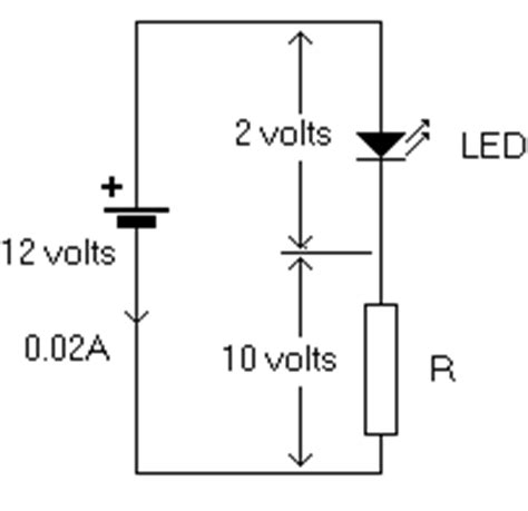
- Current-limiting resistors: LEDs require a specific amount of current to operate properly. Current-limiting resistors are used to control the current flowing through the LEDs and prevent them from being damaged by excessive current.
- LEDs: The schematic should show the number and arrangement of the LEDs, as well as their polarity (anode and cathode).
- Additional components: Depending on the application, the schematic may include additional components such as switches, sensors, or microcontrollers.
PCB Layout
Once the schematic is complete, the next step is to design the physical layout of the LEDs circuit board. The PCB layout should consider the following factors:
- Component placement: The components should be arranged in a logical and efficient manner, minimizing the distance between related components and avoiding potential interference.
- Trace width and spacing: The width and spacing of the copper traces on the PCB should be appropriate for the current requirements of the LEDs. Wider traces can handle higher currents, while narrower traces are suitable for lower currents.
- Thermal management: LEDs generate heat during operation, which can affect their performance and lifespan. The PCB layout should incorporate thermal management techniques, such as using a heatsink or designing the board to dissipate heat effectively.
- Manufacturability: The PCB layout should adhere to the design rules and guidelines specified by the PCB manufacturer to ensure that the board can be successfully fabricated.
Selecting the Right Components
Choosing the appropriate components for your LEDs circuit board is crucial for its performance and reliability. When selecting components, consider the following factors:
- LED specifications: Choose LEDs that meet your requirements for brightness, color, viewing angle, and forward voltage.
- Current-limiting resistors: Select resistors with the appropriate resistance value and power rating to control the current flowing through the LEDs.
- Power supply: Ensure that the power supply can provide the necessary voltage and current to drive the LEDs. Consider the efficiency and regulation of the power supply, as well as any additional features such as over-voltage protection.
- PCB material: Choose a PCB material that is suitable for your application. Common materials include FR-4, which is a glass-reinforced epoxy laminate, and aluminum, which offers better thermal conductivity for heat dissipation.

3. LEDs Circuit Board Manufacturing Process
PCB Fabrication
The manufacturing process for LEDs circuit boards involves several steps:
- PCB design: The PCB layout is created using computer-aided design (CAD) software, which generates the necessary files for manufacturing.
- PCB fabrication: The PCB is fabricated using a process called photolithography, which involves applying a photoresist layer to a copper-clad substrate, exposing it to UV light through a photomask, and etching away the unwanted copper to create the desired traces and pads.
- Solder mask application: A solder mask layer is applied to the PCB to protect the copper traces and prevent short circuits. The solder mask also provides insulation and improves the board’s appearance.
- Silkscreen printing: A silkscreen layer is printed on the PCB to add text, logos, and component outlines, making it easier to assemble and troubleshoot the board.
Component Assembly
Once the PCB is fabricated, the components are assembled onto the board using one of two methods:
- Through-hole assembly: Through-hole components have long leads that are inserted into holes drilled in the PCB and soldered on the opposite side. This method is suitable for larger components and is often used for prototyping or low-volume production.
- Surface-mount assembly: Surface-mount components are smaller and have flat contacts that are soldered directly onto the pads on the PCB surface. This method is more common in high-volume production and allows for higher component density and smaller board sizes.
Quality Control and Testing
After the components are assembled, the LEDs circuit board undergoes quality control and testing to ensure that it functions as intended. This process may include:
- Visual inspection: The board is visually inspected for any defects, such as incorrect component placement, solder bridges, or damaged components.
- Electrical testing: The board is powered on and tested for proper functionality, including LED brightness, color, and any additional features such as dimming or color-changing.
- Burn-in testing: The board may be subjected to a burn-in test, where it is operated for an extended period to identify any early failures or performance issues.

4. LEDs Circuit Board Applications
LEDs circuit boards are used in a wide range of applications, from consumer electronics to industrial and automotive systems. Some common applications include:
Lighting
LEDs are increasingly used in lighting applications due to their energy efficiency, long lifespan, and versatile color options. LEDs circuit boards are used in:
- Residential lighting: LED bulbs and fixtures are replacing traditional incandescent and fluorescent lamps in homes, providing energy savings and longer lifespans.
- Commercial lighting: LEDs are used in office buildings, retail stores, and restaurants for general illumination and accent lighting.
- Industrial lighting: LEDs are used in factories, warehouses, and other industrial settings for high-bay and low-bay lighting, as well as task lighting for specific work areas.
- Automotive lighting: LEDs are used in headlights, taillights, and interior lighting for vehicles, providing improved visibility and styling options.
Displays
LEDs circuit boards are used in various display applications, including:
- LED signs: LED signs are used for advertising, information displays, and traffic control, offering high visibility and low power consumption.
- LED video walls: Large-scale LED video walls are used for events, concerts, and digital signage, providing high-resolution images and vibrant colors.
- Wearable displays: LEDs are used in smartwatches, fitness trackers, and other wearable devices to provide information and notifications to users.
Indicators and Backlighting
LEDs are commonly used as indicators and for backlighting in electronic devices, such as:
- Status indicators: LEDs are used to indicate the power status, charging status, or other conditions in devices like smartphones, laptops, and appliances.
- Keyboard backlighting: LEDs are used to backlight the keys on computer keyboards, making them easier to use in low-light conditions.
- Display backlighting: LEDs are used as backlights for LCD displays in televisions, monitors, and mobile devices, providing even illumination and improved contrast.
5. Thermal Management for LEDs Circuit Boards
Importance of Thermal Management
Proper thermal management is crucial for the performance and longevity of LEDs circuit boards. LEDs generate heat during operation, and if this heat is not effectively dissipated, it can lead to several issues:
- Reduced light output: As the temperature of an LED increases, its light output decreases. This phenomenon is known as thermal droop and can result in a significant reduction in brightness if the heat is not properly managed.
- Shortened lifespan: High temperatures can cause premature degradation of the LED, reducing its lifespan. Proper thermal management helps to maintain the LED’s operating temperature within its specified range, ensuring optimal performance and longevity.
- Color shift: The color of an LED can shift slightly as its temperature changes. This can be problematic in applications where precise color control is required, such as in displays or color-critical lighting.
Thermal Management Techniques
Several thermal management techniques can be employed to ensure that LEDs circuit boards operate within their optimal temperature range:
- Heatsinks: Heatsinks are passive cooling devices that dissipate heat from the LEDs to the surrounding environment. They are typically made of materials with high thermal conductivity, such as aluminum or copper, and feature fins or other structures to increase the surface area for heat dissipation.
- Thermal interface materials (TIMs): TIMs are used to improve the thermal contact between the LED and the heatsink. They help to fill any air gaps and reduce thermal resistance, allowing heat to be transferred more efficiently from the LED to the heatsink. Common TIMs include thermal paste, thermal pads, and phase-change materials.
- PCB design: The PCB layout can be optimized for thermal management by using thicker copper layers, designing wider traces for high-current paths, and incorporating thermal vias to transfer heat from the LEDs to the heatsink or other cooling solutions.
- Active cooling: In some high-power applications, active cooling solutions may be necessary to maintain the LEDs at their optimal operating temperature. These solutions include fans, thermoelectric coolers (TECs), and liquid cooling systems.
Thermal Simulation and Testing
To ensure that an LEDs circuit board’s thermal management solution is effective, thermal simulation and testing can be performed during the design and prototyping stages:
- Thermal simulation: Thermal simulation software can be used to model the heat transfer and temperature distribution in an LEDs circuit board. This allows designers to optimize the placement of components, evaluate different heatsink designs, and identify potential hot spots before the board is manufactured.
- Thermal testing: Once a prototype board is fabricated, thermal testing can be performed to validate the thermal simulation results and ensure that the LEDs operate within their specified temperature range. This can involve using thermocouples, thermal cameras, or other temperature measurement tools to monitor the board’s temperature under various operating conditions.
By employing appropriate thermal management techniques and conducting thorough thermal simulation and testing, designers can ensure that LEDs circuit boards operate reliably and efficiently, even in demanding applications.
6. Dimming and Color Control for LEDs Circuit Boards
Dimming Techniques
Dimming LEDs allows for greater control over the light output and can create various lighting effects. There are two primary methods for dimming LEDs:
- Pulse-Width Modulation (PWM) dimming: PWM dimming involves rapidly turning the LED on and off at a high frequency, with the duty cycle (the ratio of on-time to total cycle time) determining the perceived brightness. By varying the duty cycle, the LED’s brightness can be adjusted from 0% to 100%. PWM dimming is popular because it maintains the LED’s color consistency across the dimming range and is relatively easy to implement using microcontrollers or dedicated LED drivers.
- Analog dimming: Analog dimming, also known as current dimming, involves varying the forward current through the LED to control its brightness. As the current is reduced, the LED’s brightness decreases. Analog dimming can be achieved using adjustable current sources or by varying the voltage across a current-limiting resistor. While analog dimming is simpler to implement than PWM dimming, it can cause slight color shifts in the LED as the current is reduced.
Color Control
LEDs are available in a wide range of colors, and by combining different colored LEDs or using multi-color LEDs, various color-changing effects can be achieved. There are several methods for controlling the color of LEDs:
- RGB LEDs: RGB LEDs contain three separate LED chips (red, green, and blue) in a single package. By independently controlling the brightness of each chip using PWM dimming, a wide range of colors can be produced. This is achieved by mixing different ratios of red, green, and blue light, a process known as additive color mixing.
- WS2812B LEDs (NeoPixels): WS2812B LEDs, also known as NeoPixels, are intelligent RGB LEDs that contain an integrated controller. Each LED can be individually addressed and controlled using a single-wire protocol, allowing for easy creation of complex color patterns and animations. WS2812B LEDs are popular in applications such as LED strips, displays, and wearable electronics.
- Color-temperature-adjustable white LEDs: Some white LEDs are available with adjustable color temperature, allowing the user to vary the warmth or coolness of the light. These LEDs typically contain two separate LED chips (warm white and cool white) that can be independently controlled using PWM dimming to achieve the desired color temperature.
Dimming and Color Control Circuits
To implement dimming and color control in LEDs circuit boards, additional components and circuitry are required:
- PWM controllers: PWM controllers generate the necessary PWM signals to control the brightness of the LEDs. These can be dedicated LED driver ICs or microcontrollers programmed to generate PWM signals.
- Current-limiting resistors: Current-limiting resistors are used to control the maximum current flowing through the LEDs, protecting them from damage and ensuring consistent brightness across multiple LEDs.
- Transistors or MOSFETs: Transistors or MOSFETs are used as switches to control the flow of current through the LEDs. They are typically controlled by the PWM signals from the controller.
- Decoder ICs: In applications using WS2812B LEDs, decoder ICs are used to convert the single-wire control signal into the individual control signals for each LED in the chain.
By incorporating dimming and color control circuitry into LEDs circuit boards, designers can create dynamic and visually appealing lighting effects that can be customized for various applications.
7. LEDs Circuit Board Design Software and Tools
Designing LEDs circuit boards requires specialized software and tools to create schematics, lay out PCBs, and perform simulations. Some popular options include:
Schematic Capture Software
- KiCad: KiCad is a free, open-source software suite for electronic design automation (EDA). It includes a schematic capture tool, PCB layout editor, and other utilities for creating LEDs circuit boards.
- Eagle: Eagle is a widely-used EDA software package that offers schematic capture, PCB layout, and library management tools. It is available in both free and paid versions, with the free version having limitations on board size and layer count.
- OrCAD Capture: OrCAD Capture is a professional-grade schematic capture tool that is part of the OrCAD EDA suite. It offers advanced features and integrates with other OrCAD tools for PCB layout and simulation.
PCB Layout Software
- KiCad: In addition to its schematic capture tool, KiCad includes a PCB layout editor for designing the physical layout of LEDs circuit boards.
- Eagle: Eagle’s PCB layout editor is tightly integrated with its schematic capture tool, allowing for seamless transfer of design data between the two environments.
- Altium Designer: Altium Designer is a high-end PCB design software package that offers advanced features for complex designs, including 3D modeling, signal integrity analysis, and design rule checking.
Simulation Tools
- LTspice: LTspice is a free, SPICE-based analog circuit simulation program that can be used to simulate the behavior of LEDs circuit boards. It is particularly useful for analyzing the
No responses yet