Introduction to Rigid-Flex PCBs
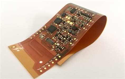
Rigid-Flex PCBs are a unique type of printed circuit board that combines the best features of both rigid and flexible PCBs. These hybrid boards consist of rigid and flexible substrates that are laminated together, allowing for three-dimensional packaging and improved reliability in demanding applications. Rigid-Flex PCBs offer several advantages over traditional PCBs, including:
- Reduced weight and space requirements
- Improved electrical performance
- Enhanced mechanical stability
- Increased design flexibility
- Better thermal management
The use of Rigid-Flex PCBs has grown significantly in recent years, particularly in industries such as aerospace, automotive, medical devices, and consumer electronics. As electronic devices become smaller, more complex, and more reliable, Rigid-Flex PCBs provide a viable solution for meeting these challenges.
Rigid-Flex PCB Structure
A Rigid-Flex PCB typically consists of the following layers:
-
Rigid layers: These are the standard FR-4 or high-frequency materials used in traditional rigid PCBs. They provide mechanical support and house most of the components.
-
Flexible layers: These are made from thin, flexible materials such as polyimide (PI) or polyester (PET). They allow the board to bend and flex as needed.
-
Adhesive layers: These layers bond the rigid and flexible sections together, ensuring a strong and reliable connection.
-
Coverlay: A protective layer that covers the flexible portions of the board, providing insulation and mechanical protection.
The number and arrangement of these layers can vary depending on the specific application and design requirements.

Rigid-Flex PCB Manufacturing Process
The manufacturing process for Rigid-Flex PCBs is more complex than that of standard rigid PCBs due to the inclusion of flexible layers and the need for precise alignment and lamination. The general steps involved in Rigid-Flex PCB manufacturing are as follows:
-
Design and layout: The PCB Design is created using specialized CAD software, taking into account the unique requirements of Rigid-Flex boards, such as bend radius, layer stackup, and material selection.
-
Material selection: The appropriate rigid and flexible materials are chosen based on the application’s requirements, such as temperature range, electrical performance, and mechanical durability.
-
Flexible circuit fabrication: The flexible layers are produced by etching the conductive pattern onto the flexible substrate, such as polyimide or polyester.
-
Rigid circuit fabrication: The rigid layers are manufactured using standard PCB fabrication techniques, such as etching, drilling, and plating.
-
Lamination: The rigid and flexible layers are aligned and laminated together using heat and pressure, with adhesive layers placed between them to ensure a strong bond.
-
Drilling and plating: Holes are drilled through the laminated board, and the holes are plated to create electrical connections between layers.
-
Solder mask and silkscreen: A solder mask is applied to protect the board from oxidation and prevent short circuits, while a silkscreen layer is added for component labeling and identification.
-
Surface finishing: The exposed copper surfaces are coated with a protective finish, such as HASL, ENIG, or OSP, to prevent oxidation and improve solderability.
-
Profiling and routing: The board is cut and shaped to its final dimensions using CNC machines or laser cutting equipment.
-
Electrical testing: The completed Rigid-Flex PCB undergoes thorough electrical testing to ensure proper functionality and adherence to specifications.
Rigid-Flex PCB Manufacturing Challenges
While Rigid-Flex PCBs offer numerous benefits, their manufacturing process presents several challenges that must be addressed to ensure a high-quality final product:
-
Material compatibility: Ensuring that the rigid and flexible materials are compatible and can withstand the lamination process without delamination or damage.
-
Alignment: Maintaining precise alignment between the rigid and flexible layers during lamination to avoid misregistration and ensure proper electrical connections.
-
Bend radius: Designing the flexible portions with an appropriate bend radius to prevent damage or fatigue during flexing.
-
Adhesive selection: Choosing the right adhesive that provides strong bonding between layers while maintaining flexibility and durability.
-
Coverlay application: Applying the coverlay material evenly and without air bubbles or wrinkles to protect the flexible circuits.
Overcoming these challenges requires careful design, material selection, and process control throughout the manufacturing process.

Rigid-Flex PCB Applications
Rigid-Flex PCBs are used in a wide range of industries and applications where traditional rigid PCBs may not be suitable. Some common applications include:
- Aerospace and defense:
- Avionics systems
- Satellites and space vehicles
- Military communication devices
-
Radar and surveillance equipment
-
Automotive:
- Engine control units (ECUs)
- Infotainment systems
- Driver assistance systems (ADAS)
-
Electric and hybrid vehicle batteries
-
Medical devices:
- Implantable devices (e.g., pacemakers, defibrillators)
- Wearable health monitors
- Portable medical equipment
-
Surgical instruments
-
Consumer electronics:
- Smartphones and tablets
- Wearable devices (e.g., smartwatches, fitness trackers)
- VR and AR headsets
-
Laptops and portable gaming devices
-
Industrial automation:
- Robotics and motion control systems
- Sensors and data acquisition devices
- Industrial IoT devices
- Process control equipment
These applications often require high reliability, compact packaging, and the ability to withstand harsh environments, making Rigid-Flex PCBs an ideal solution.

Advantages of Rigid-Flex PCBs
Rigid-Flex PCBs offer several key advantages over traditional rigid PCBs:
-
Space and weight reduction: By combining rigid and flexible sections, Rigid-Flex PCBs can be packaged in more compact and lightweight forms, saving valuable space in electronic devices.
-
Improved reliability: The flexible sections of Rigid-Flex PCBs can absorb stress and vibration, reducing the risk of mechanical failure and improving overall reliability.
-
Enhanced electrical performance: The shorter signal paths and reduced interconnections in Rigid-Flex PCBs can lead to better signal integrity and reduced electromagnetic interference (EMI).
-
Design flexibility: Rigid-Flex PCBs allow for three-dimensional packaging and the ability to conform to complex shapes, enabling more innovative and efficient product designs.
-
Cost reduction: While the initial cost of Rigid-Flex PCBs may be higher than traditional PCBs, they can lead to cost savings in the long run by reducing the number of connectors, cables, and assembly steps required.
Rigid-Flex PCB Design Considerations
Designing Rigid-Flex PCBs requires careful consideration of several factors to ensure optimal performance and manufacturability:
-
Bend radius: The minimum bend radius must be determined based on the thickness and material properties of the flexible layers to prevent damage or fatigue during flexing.
-
Layer stackup: The arrangement of rigid and flexible layers must be carefully planned to ensure proper electrical connections and mechanical stability.
-
Material selection: Choosing the right materials for the rigid and flexible sections is crucial for ensuring compatibility, reliability, and performance in the intended application environment.
-
Conductor width and spacing: The width and spacing of conductors on the flexible layers must be designed to accommodate bending and flexing without causing damage or short circuits.
-
Adhesive selection: The adhesive used to bond the layers must provide strong adhesion while maintaining flexibility and durability over the product’s lifetime.
-
Coverlay design: The coverlay material and design must be selected to provide adequate protection for the flexible circuits without impeding flexibility or adding excessive thickness.
-
Component placement: Components should be placed on the rigid sections of the board whenever possible to avoid stress on the components during flexing.
-
Transition zones: The transition areas between rigid and flexible sections must be carefully designed to minimize stress and ensure reliable electrical connections.
-
Manufacturing constraints: The design must take into account the capabilities and limitations of the manufacturing process, such as minimum feature sizes, layer counts, and tolerances.
Rigid-Flex PCB Testing and Quality Control
Ensuring the quality and reliability of Rigid-Flex PCBs requires thorough testing and quality control measures throughout the manufacturing process:
-
Visual inspection: Boards are visually inspected for defects such as misalignment, delamination, or damage to the flexible sections.
-
Electrical testing: Continuity, isolation, and resistance tests are performed to verify proper electrical connections and identify any short circuits or open connections.
-
Mechanical testing: Boards are subjected to bending and flexing tests to ensure they can withstand the expected mechanical stresses without damage or failure.
-
Environmental testing: Boards are exposed to various environmental conditions, such as temperature cycling, humidity, and vibration, to validate their performance and reliability in the intended application environment.
-
Microsectioning: Cross-sections of the board are examined under a microscope to verify proper layer alignment, adhesion, and the integrity of plated through-holes.
-
Functional testing: The completed Rigid-Flex PCB is tested in the final product or a representative test setup to ensure proper functionality and performance.
Implementing a comprehensive quality control plan helps identify and address any issues early in the manufacturing process, reducing the risk of costly failures or product recalls.
Future Trends in Rigid-Flex PCB Technology
As electronic devices continue to advance and evolve, Rigid-Flex PCB technology must keep pace to meet the growing demands for performance, reliability, and functionality. Some key trends shaping the future of Rigid-Flex PCBs include:
-
Advanced materials: The development of new materials with improved electrical, thermal, and mechanical properties will enable Rigid-Flex PCBs to be used in even more demanding applications.
-
High-speed design: As data rates continue to increase, Rigid-Flex PCBs will need to be designed to support higher frequencies and minimize signal integrity issues.
-
Miniaturization: The trend towards smaller, more compact electronic devices will drive the need for even more advanced Rigid-Flex PCB packaging solutions.
-
Wearable electronics: The growth of wearable devices and the Internet of Things (IoT) will create new opportunities for Rigid-Flex PCBs in applications that require flexibility, durability, and low power consumption.
-
Embedded components: Integrating passive and active components directly into the Rigid-Flex PCB structure will enable further miniaturization and performance improvements.
-
Additive manufacturing: The use of 3D printing and other additive manufacturing techniques may enable new Rigid-Flex PCB designs and faster prototyping.
-
Sustainable manufacturing: As environmental concerns continue to grow, there will be an increased focus on developing eco-friendly materials and manufacturing processes for Rigid-Flex PCBs.
By staying at the forefront of these trends, Rigid-Flex PCB manufacturers and designers will be well-positioned to meet the evolving needs of the electronics industry.
Frequently Asked Questions (FAQ)
-
What is a Rigid-Flex PCB?
A Rigid-Flex PCB is a hybrid printed circuit board that combines rigid and flexible substrates, allowing for three-dimensional packaging and improved reliability in demanding applications. -
What are the advantages of using Rigid-Flex PCBs?
Rigid-Flex PCBs offer several advantages, including reduced weight and space requirements, improved electrical performance, enhanced mechanical stability, increased design flexibility, and better thermal management. -
In what industries are Rigid-Flex PCBs commonly used?
Rigid-Flex PCBs are used in various industries, such as aerospace, automotive, medical devices, consumer electronics, and industrial automation, where high reliability, compact packaging, and the ability to withstand harsh environments are essential. -
What are the key challenges in manufacturing Rigid-Flex PCBs?
The main challenges in manufacturing Rigid-Flex PCBs include ensuring material compatibility, maintaining precise alignment between layers, designing appropriate bend radii, selecting the right adhesive, and applying the coverlay material properly. -
What are some future trends in Rigid-Flex PCB technology?
Future trends in Rigid-Flex PCB technology include the development of advanced materials, high-speed designs, further miniaturization, growth in wearable electronics, embedded components, additive manufacturing, and sustainable manufacturing practices.
Conclusion
Rigid-Flex PCBs have emerged as a key enabling technology for the electronics industry, offering a unique combination of flexibility, reliability, and performance. By understanding the manufacturing process, design considerations, and quality control measures involved in Rigid-Flex PCB production, engineers and manufacturers can harness the full potential of this technology to create innovative and high-quality electronic products.
As the demands for smaller, more complex, and more reliable electronic devices continue to grow, Rigid-Flex PCBs will play an increasingly important role in shaping the future of the industry. By staying at the forefront of emerging trends and technologies, Rigid-Flex PCB manufacturers and designers can position themselves for success in this dynamic and rapidly evolving field.
No responses yet